4.4 Fluid Dynamics: Component-Propeller
1. Geometry
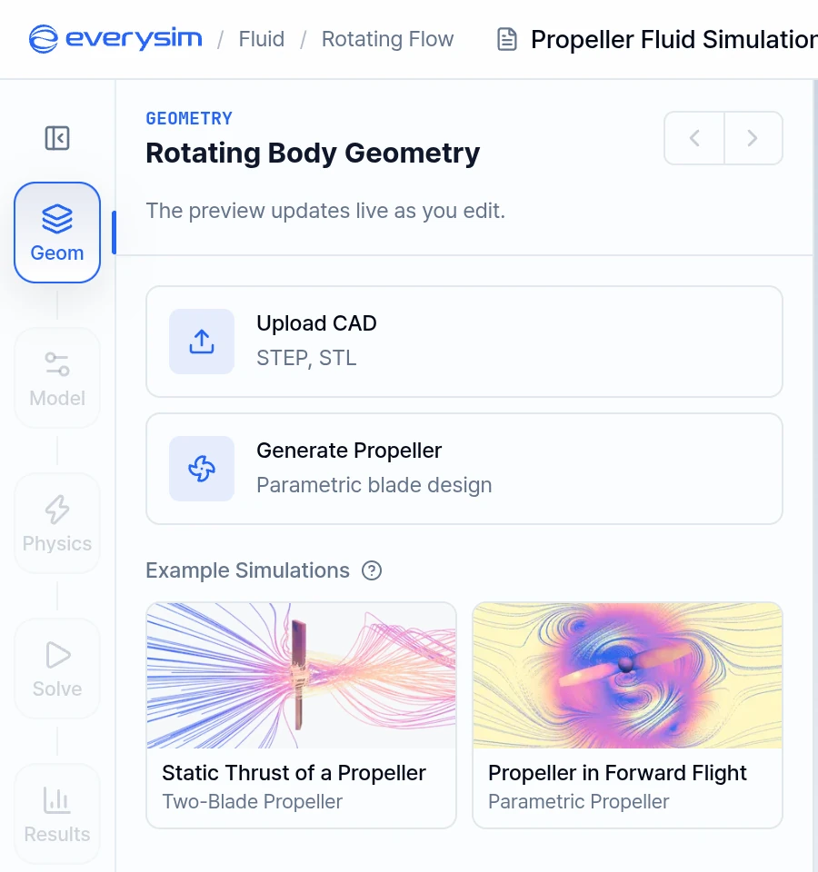
The Geometry step supports two sources: Generate Propeller and Upload CAD.
1.1. Generate Propeller
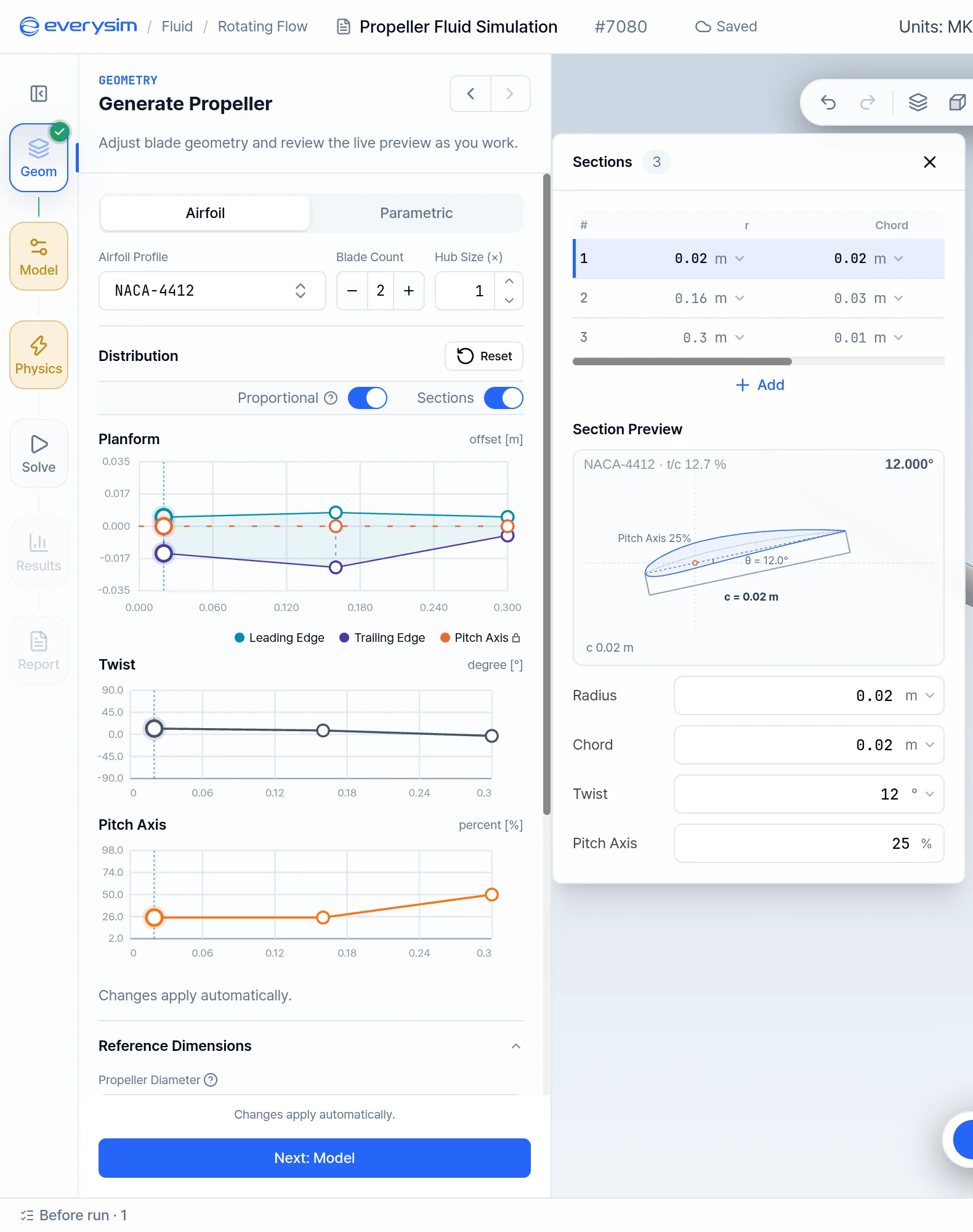
The editor has two modes: Airfoil (default) and Parametric. Valid changes are applied automatically and update the preview, so there is no button to generate the geometry.
1.1.1. Airfoil Mode
Choose an Airfoil Profile, set Blade Count (up to 12) and Hub Size (×), then shape the blade with the Distribution charts or the Sections table:
- r: Radius of the section
- Chord: Chord length at the section
- Twist: Twist angle in degrees
- Pitch Axis: Pitch axis position, as a percentage of the chord
The Section Preview shows the selected section.
1.1.2. Parametric Mode
Parametric mode defines the Root, Middle and Side sections, the blade count and the hub. Each section has the same fields:
- Length: Section length
- α: Angle of attack
- β: Pitch angle
- R_L: Left radius
- R_R: Right radius
- R_C: Center radius
- Distance: Section distance
- Depth: Section depth
α + β must not exceed 90°.
The blade count and hub settings are:
- Blade Count: Total number of blades
- Hub Cap: Whether to include a cap at the hub center
- Hub > Outer: Hub outer radius
- Hub > Inner: Hub inner radius
- Hub > Height: Hub height
1.2. Upload CAD
Click Upload CAD, then drag a file in, click Browse Files, or choose the Propeller sample. Supported formats are STEP, STP, IGES, IGS, BREP and STL. Confirm the length unit if asked.
After the import, the app checks the geometry and reports any health issues on this step. The Simulation on Your CAD page explains how to resolve them.
1.3. Rotation Configuration
For uploaded CAD, Rotation Configuration sets the Rotation Axis (X, Y or Z, Auto by default), its Axis Sign and the rotation Direction. A generated propeller spins about its build axis, so this section does not appear for it.
1.4. Reference Dimensions
- Propeller Diameter: Normalizes thrust, torque and power metrics. For imported CAD, the automatically calculated value may differ from the actual diameter. Check it and enter the correct value if you know it.
- Thrust Direction: The way the propeller is meant to push. Thrust along it reads as positive in the report.
- Blade Count: For imported CAD, this value is shown in the report and does not change the results.
- Add Blade-Section Data: Enter Chord Length and Chord Measurement Radius to get a Reynolds number in the report.
Click Next: Model to continue.
2. Model: Fluid & Rotating Zone
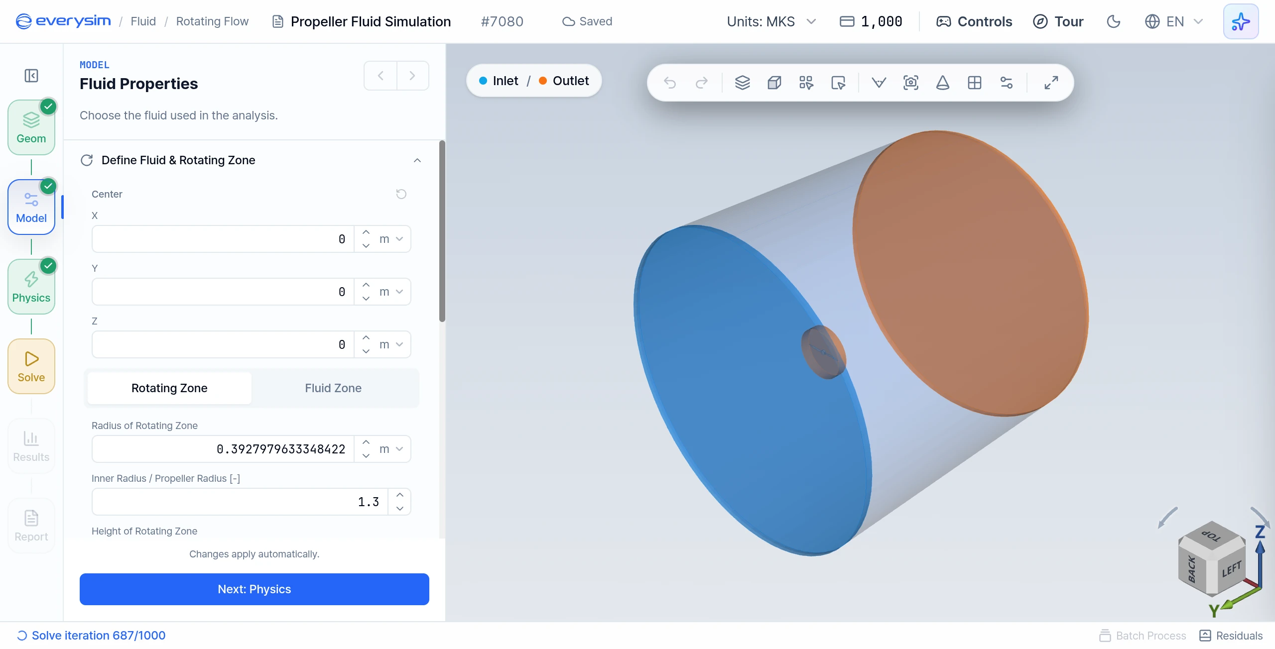
Opening the Model step creates the zone from the geometry. Adjust it in Define Fluid & Rotating Zone. The panel heading on this step reads Fluid Properties.
2.1. Fluid Properties
Choose Air, Water or Custom. This changes the coefficients and the Reynolds number.
2.2. Center
Center X, Y and Z set the position of the zone, above the two tabs.
2.3. Rotating Zone
The tab for the inner region that wraps around and rotates with the propeller.
- Radius of Rotating Zone: Radius of the rotating region
- Inner Radius / Propeller Radius: Ratio of that radius to the propeller radius
- Height of Rotating Zone: Axial length of the rotating region
- Inner Height / Propeller Radius: Ratio of that height to the propeller radius
2.4. Fluid Zone
The tab for the surrounding stationary region.
- Radius of Fluid Zone: Radius of the outer region
- Outer Radius / Propeller Radius: Ratio of that radius to the propeller radius
- Height of Fluid Zone Front: Axial length in front of the propeller
- Outer Front Height / Propeller Radius: Ratio of the front height to the propeller radius
- Height of Fluid Zone Back: Axial length behind the propeller
- Outer Back Height / Propeller Radius: Ratio of the back height to the propeller radius
Lengths follow the Units selector in the top bar.
2.5. Wake Refinement
Wake Refinement refines the mesh in the wake, the air the rotor pushes back. Thrust and torque are more accurate, but the run takes longer.
3. Physics: Flow Conditions
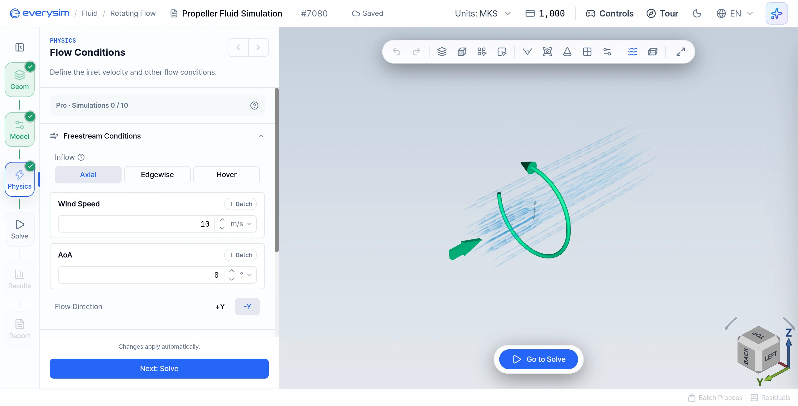
3.1. Freestream Conditions
- Inflow: Axial (the wind blows along the spin axis), Edgewise (the wind blows across the rotor disk) or Hover (still air, no wind speed).
- Wind Speed: The inflow velocity. It is hidden for Hover. Use Batch to sweep several values.
- AoA: The angle between the incoming flow and the propeller disc normal, between -90° and 90°. The Inflow presets set it.
- Flow Direction: The direction the wind travels. It is set independently of the rotation axis.
3.2. Rotation Speed and Direction
Under Rotation Conditions, set Rotation Speed and Direction (CW or CCW).
4. Solve
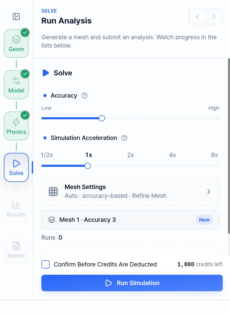
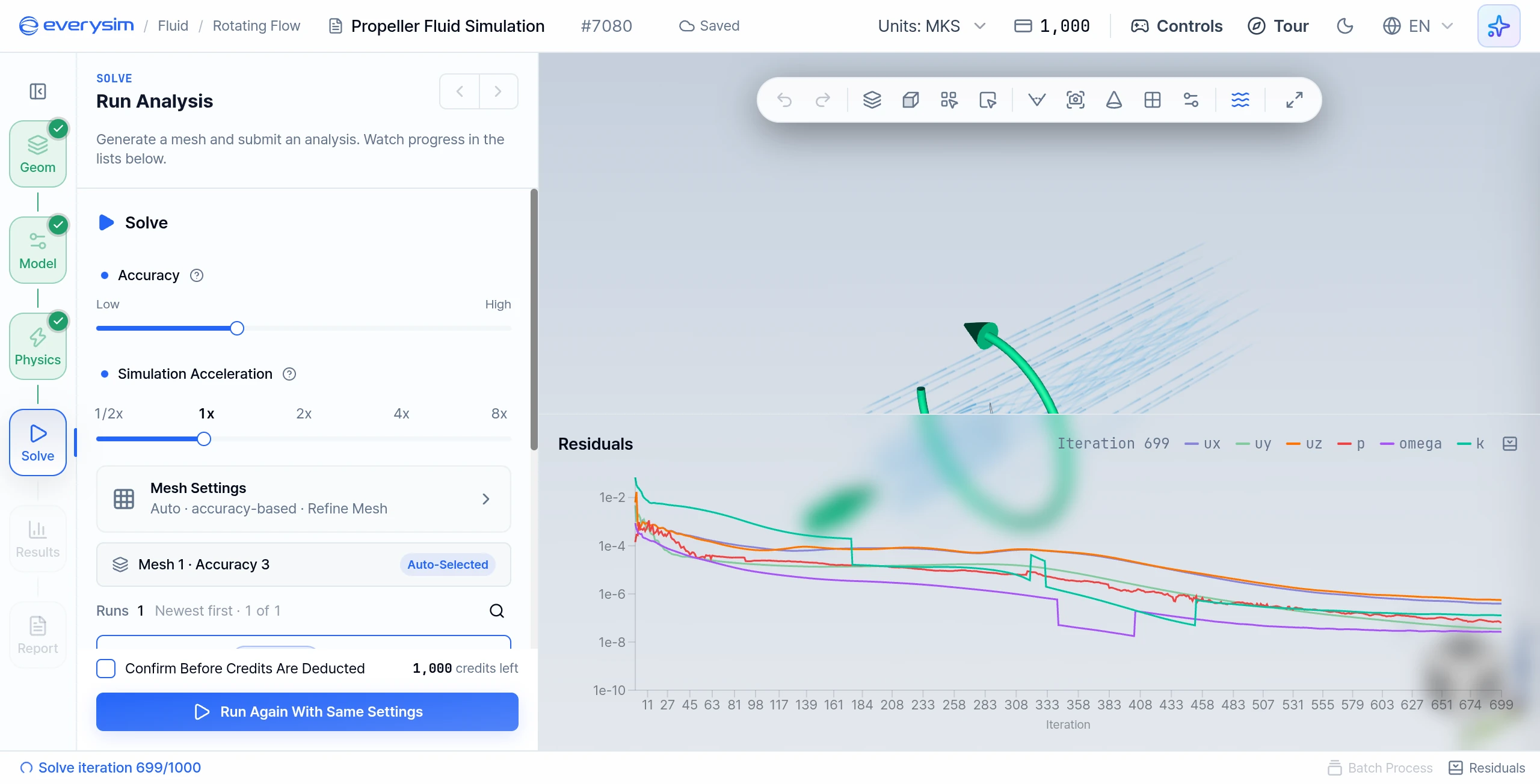
- Accuracy: A 7-step slider from Low to High. Higher accuracy gives more precise results, but takes longer and uses more credits.
- Mesh Settings: With Auto Size on, sizes follow Accuracy. With it off, the slider has no effect and you set Mesh Detail, Size Transition Smoothness, Shape Accuracy, Edge Refinement and Shape Accuracy Method (Standard, Adaptive, Precise, Maximum Precision). The toggles are Refine Mesh, Feature Smoothing and Detail Capture (Beta).
- Simulation Acceleration: 1/2x to 8x. Higher acceleration shortens the run and consumes credits faster; stops above your plan limit are locked.
Click Run Simulation to generate the mesh and solve, or Generate Mesh Only to preview the mesh first.
Tip: To check the mesh, show it on the canvas from the mesh card on Solve and use Section View (Cut or Clip) to inspect it in cross-section.
5. Residuals
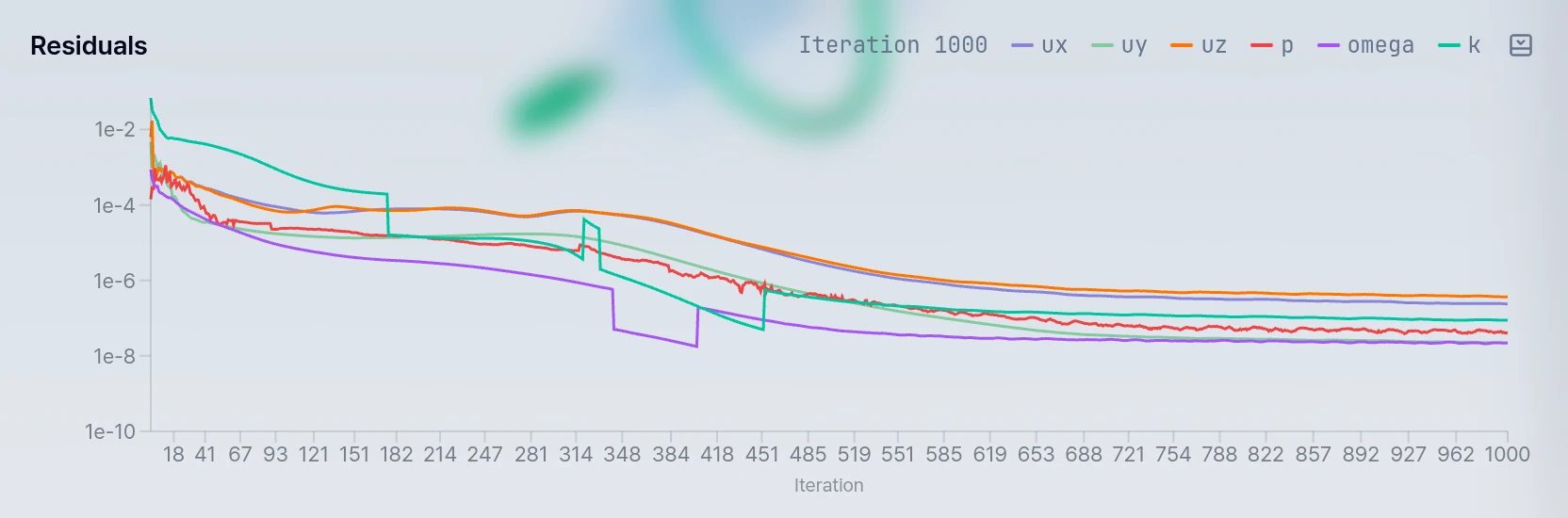
When solving starts, the Residuals chart opens at the bottom of the workbench, where you can monitor the convergence of the run. Use Residuals in the status bar to reopen it.
6. Results
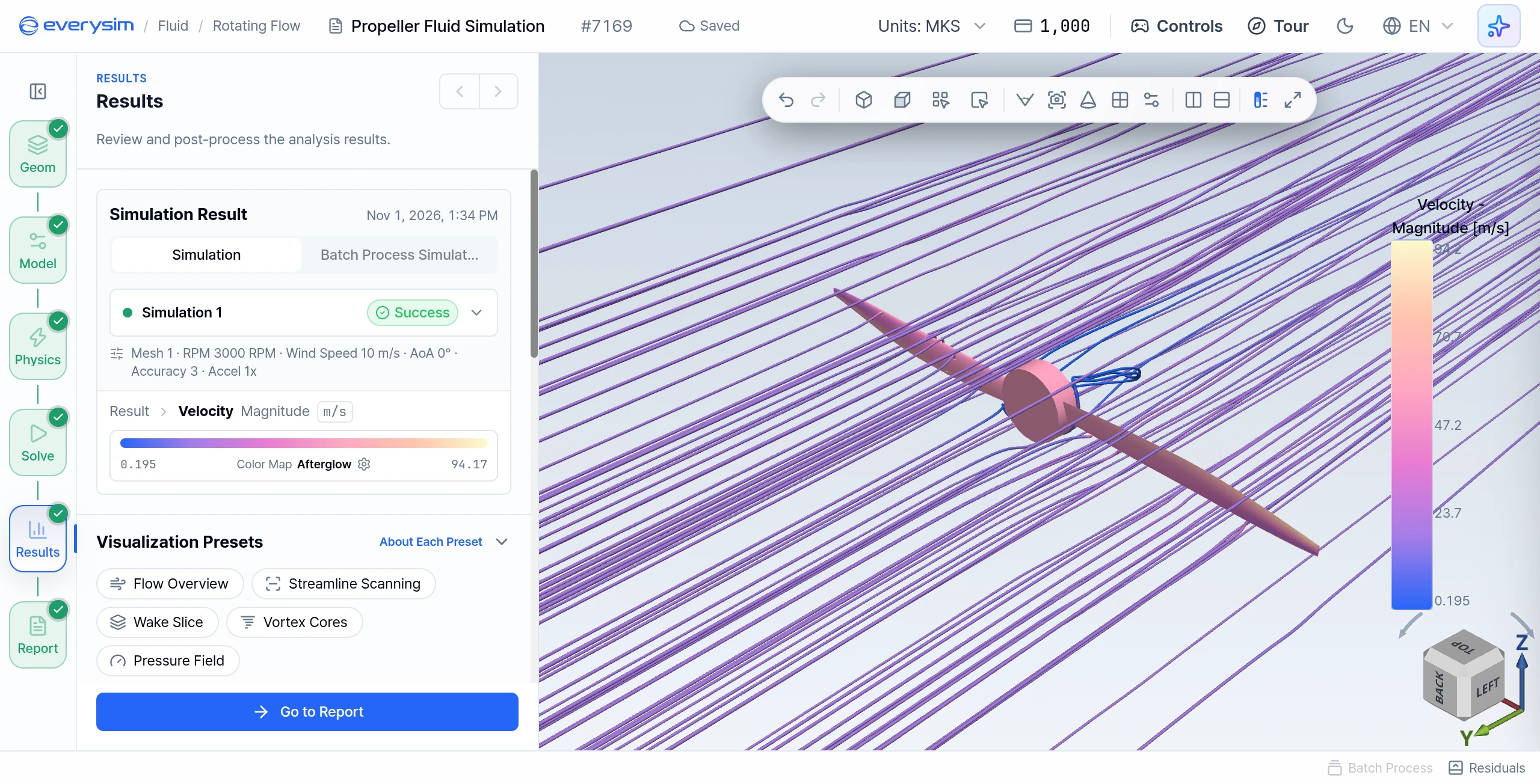
Figure 8 is from a run at 3000 RPM and 10 m/s axial inflow. The fluid domain is hidden by setting the Opacity of Result to 0 under Result Fields, with Streamline on.
In the Results step, you can visualize Velocity, Pressure, Turbulence, Vorticity, Advanced Vorticity, Wall Shear Stress and y+ as 3D contours from the Results Tree.
Turn on Streamline under Visualization Tools, or apply a Visualization Preset such as Flow Overview.
7. Report
In this section, you can evaluate propeller performance based on numerical data calculated from simulation results.
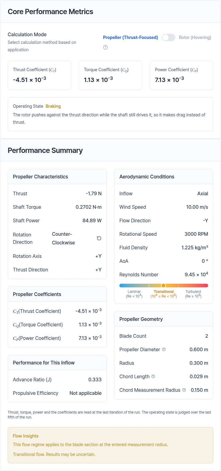
Figures 9 and 10 are from the same run as Figure 8: 3000 RPM and 10 m/s axial inflow (advance ratio 0.333). These inputs give negative thrust, -1.79 N, and the report reads Braking: the shaft still drives the rotor, at 84.89 W, but the rotor makes drag, not thrust.
7.1. Core Performance Metrics
Displays dimensionless performance coefficients.
- Thrust Coefficient: Dimensionless thrust generated by the propeller
- Torque Coefficient: Dimensionless torque required for propeller rotation
- Power Coefficient: Normalized input power value
- Calculation Mode: Propeller (Thrust-Focused) or Rotor (Hovering). The mode changes the coefficient definitions.
- Operating State: Whether the rotor is working as intended, such as Propulsive, Braking or Windmilling
7.2. Performance Summary
Summarizes key performance parameters.
7.2.1. Propeller Characteristics
- Thrust: Total axial force (propulsive force) generated by the propeller
- Shaft Torque: Propeller shaft torque due to aerodynamic drag (used for motor selection)
- Shaft Power: Mechanical input power needed to overcome torque at given RPM (P=2πnQ)
- Rotation Direction: Direction of propeller rotation (CW/CCW), affects wake and swirl
- Rotation Axis: Direction of the rotation axis (e.g., +X, +Y, etc.)
- Thrust Direction: Direction that reads as positive thrust
7.2.2. Aerodynamic Conditions
- Inflow: The inflow preset used in the run
- Wind Speed and Flow Direction: The incoming flow
- Rotational Speed: Propeller revolutions per minute, directly affects thrust and torque
- Fluid Density: Assumed fluid density (1.225 kg/m³ for default air)
- AoA: Angle between incoming flow and propeller disc normal (affects thrust generation)
- Reynolds Number: Dimensionless number based on blade chord and inflow conditions. Shown when Chord Length and Chord Measurement Radius are entered on the Geometry step.
7.2.3. Propeller Coefficients and Performance for This Inflow
Propeller Coefficients lists the thrust, torque and power coefficients. Performance for This Inflow depends on the inflow:
- Hover: Figure of Merit, the ideal hover efficiency, and Disk Loading. These apply to hover only.
- Other inflow: Advance Ratio (J), the relationship between forward velocity and propeller rotation speed, and Propulsive Efficiency, how well input power is converted to useful thrust.
- Non-axial inflow: In-Plane Force and the inflow components also appear.
7.2.4. Propeller Geometry
- Blade Count: Number of propeller blades. For imported CAD, this value is informational and does not change results.
- Propeller Diameter: Actual size of the propeller (used in all dimensionless calculations)
7.3. Force and Moment Distribution
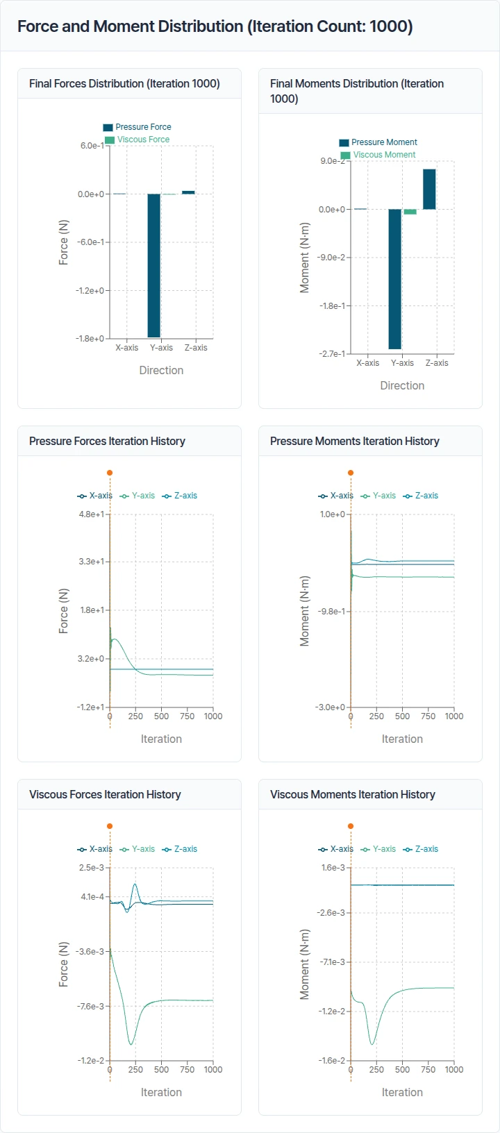
Displays total aerodynamic forces and moments broken down as follows:
- Pressure Forces: Surface forces due to static and dynamic pressure distribution
- Viscous Forces: Forces due to shear stress and fluid viscosity
- Pressure Moments: Torque due to pressure distribution on blade surfaces
- Viscous Moments: Torque due to viscous (shear) effects (generally smaller than pressure moments)
Each term is decomposed into X, Y, Z components for evaluating symmetry, imbalance, and axial loads.
7.4. Iteration History
Provides graphs of force and moment variations per iteration.
- Verify convergence
- Detect oscillations/instabilities and determine if a steady value has been reached
Need Assistance or Have Questions?
Frequently Asked Questions: FAQ Link
Support Inquiries: support@everysim.io