4.2 Structural Analysis: Component-Wing
1. Geometry
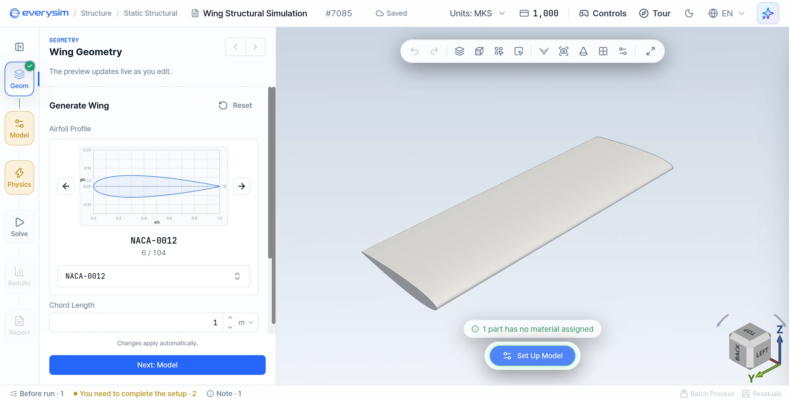
This screen shows the beginning of the structural analysis workflow for a wing component. The step rail on the left shows Geom, Model, Physics, Solve, Results and Report. A wing project has no source cards or CAD upload: the wing editor is the Geom step, and it opens with a generated wing.
1.1. Parametric Design
The wing editor lets you search and select an airfoil profile, preview its cross-sectional shape, and set the basic dimensions. These options define the wing that will be used to create the analysis model.
The main configuration items are:
- Airfoil Profile: Search and select the section to use for the wing
- Chord Length: Chord length of the wing section, at least 1 mm, in the unit shown beside the field
- Span: Extruded length of the wing, at least 1 mm, in the unit shown beside the field
- Spline: none turns B-spline interpolation off; 1-10 sets how finely the curve is sampled
Valid changes generate and save automatically, so continue with Next: Model when the shape is right.
2. Model: Material Properties
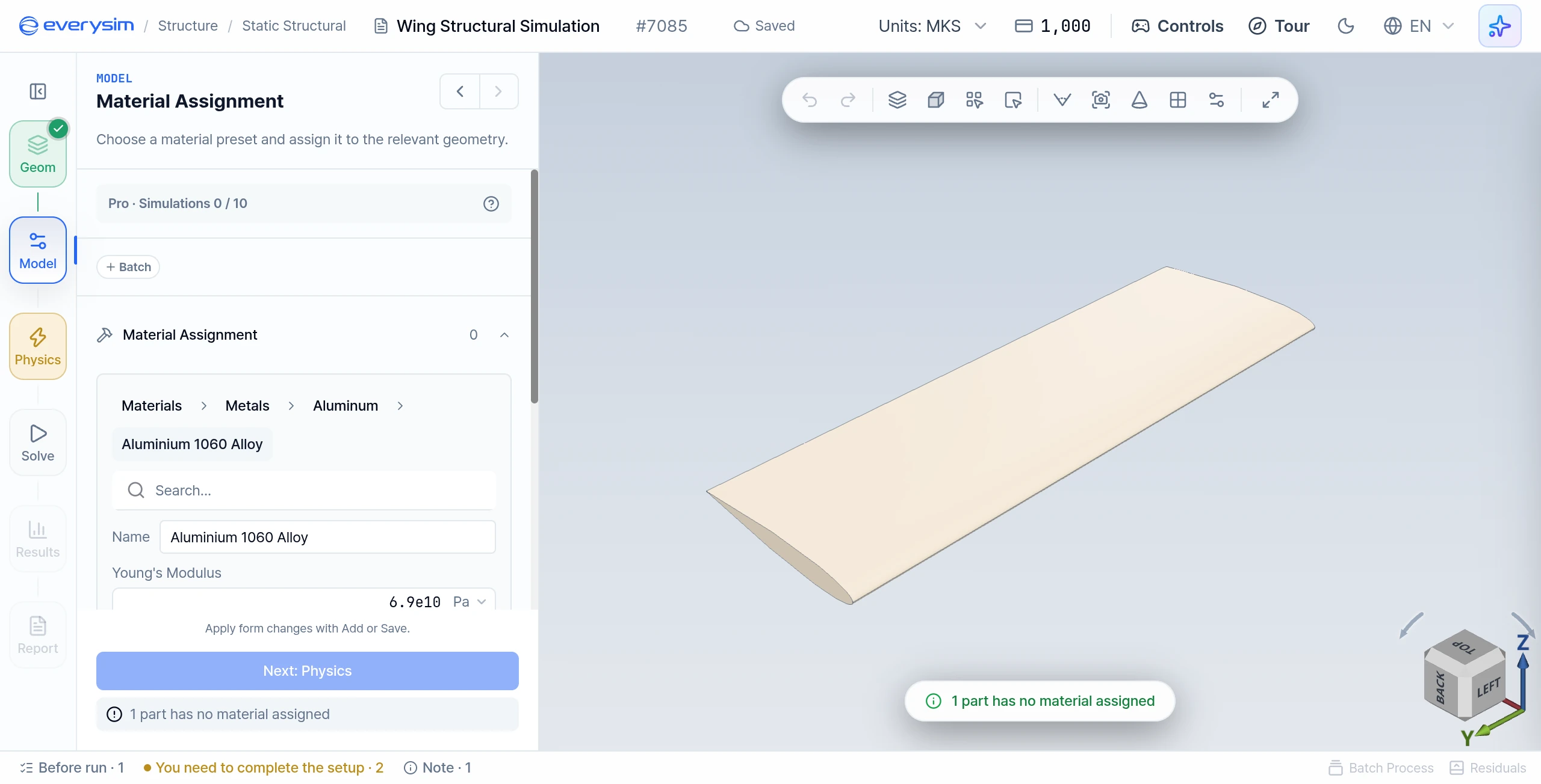
This screen shows Material Assignment in the Model step. The material form is displayed in the panel on the left, and the wing is in the viewport on the right.
Click Add Material, then choose Materials > category > family > material, or use the search box. There is no separate manual entry mode. The fields below appear once a material is selected, so for a custom material, choose the closest preset and then edit its values:
- Name: Name of the material
- Young's Modulus: Elastic stiffness of the material (above 0)
- Poisson Ratio: Ratio between lateral and axial strain (0 to below 0.5)
- Density: Mass per unit volume of the material (above 0)
- Thermal Exp.: Thermal expansion coefficient of the material. The app has no thermal load.
- Tensile Str.: Maximum tensile stress before failure
- Yield Str.: Stress level where permanent deformation begins
The generated wing is one body, so it is selected automatically. Check the highlighted body in the viewport, then click Add.
3. Physics: Boundary Conditions
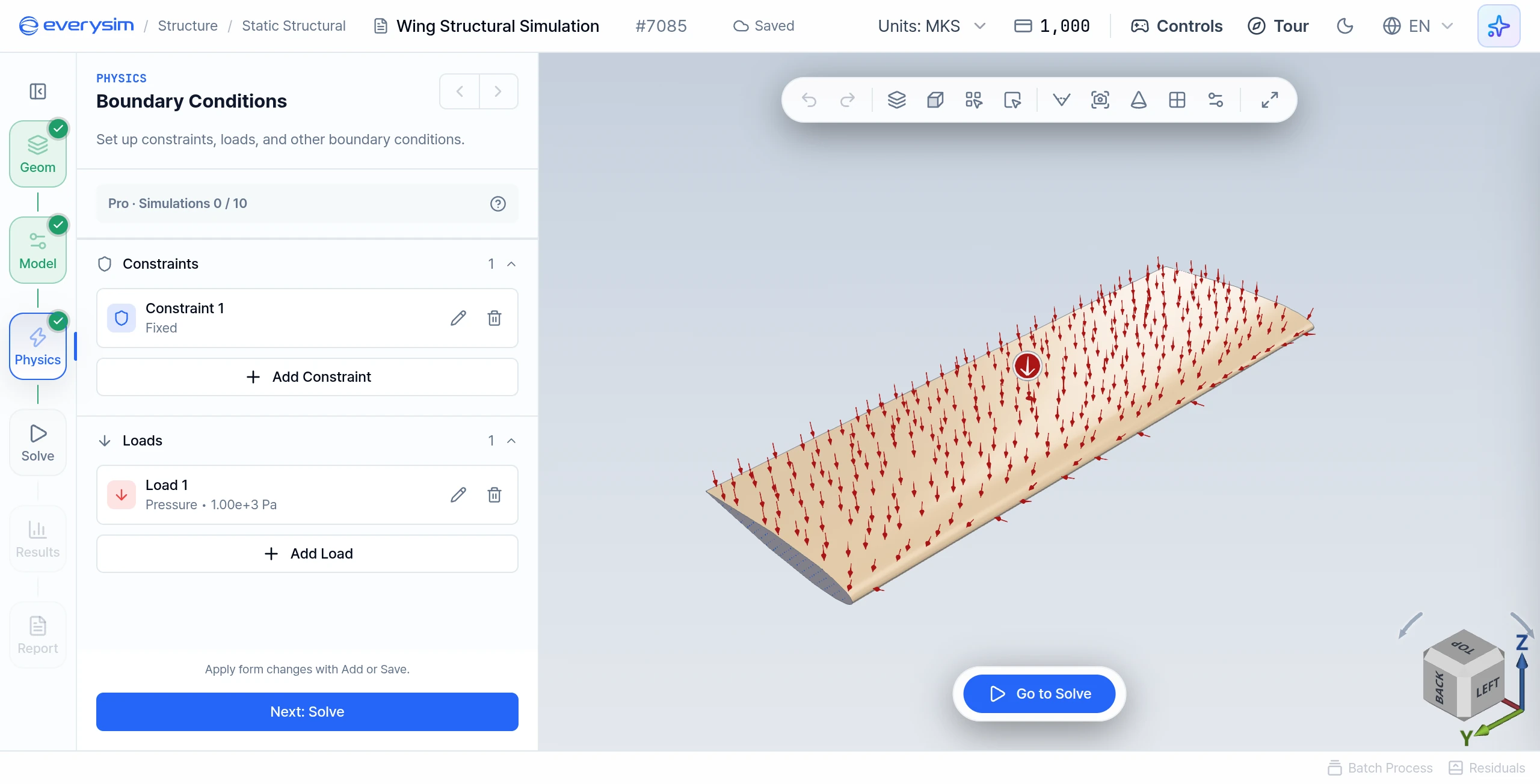
This figure shows the Boundary Conditions step with one Fixed constraint and one Pressure load applied to the wing.
Under Constraints, click Add Constraint, then set Type to Fixed or Displacement. Click faces in the viewport (hold Shift to add more), then click Add.
3.1. Fixed
Use Fixed to lock the selected faces. This is commonly applied to the root area of the wing to represent the connection to the body or fixture.
3.2. Displacement
Use Displacement when a specific displacement should be applied to the selected faces.
- Dx, Dy, Dz: Displacement per axis, in the unit shown beside the field (m in the default MKS preset)
Enter * to leave an axis free. At least one axis must be constrained.
4. Physics: Loads
The load form lets you select faces on the wing and apply a load. These load conditions represent the external forces that will be used to evaluate the wing's structural response.
Under Loads, click Add Load, then set Type to Pressure, Facial Force, Gravity or Displacement. Click faces in the viewport (hold Shift to add more), enter the values, then click Add. A run needs at least one constraint and one load.
4.1. Pressure
Use Pressure to apply a distributed load normal to the selected faces. Enter the value in Magnitude, in the unit shown beside the field (Pa in the default MKS preset).
4.2. Facial Force
Use Facial Force to apply force components directly to the selected faces.
- Fx, Fy, Fz: Force per axis, in the unit shown beside the field
4.3. Gravity and Displacement
Gravity does not need a face selection, and a model can have only one. Displacement takes the same Dx, Dy, Dz input as the displacement constraint.
5. Solve: Mesh and Accuracy
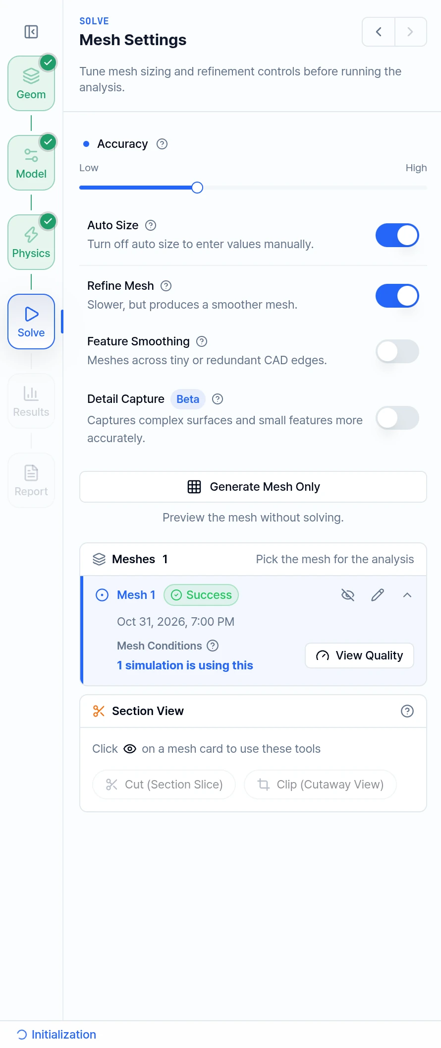
The Solve stage, headed Run Analysis, uses the same accuracy-based mesh workflow as the Structural Propeller page. Choose the accuracy level, open Mesh Settings for automatic sizing and refinement options, then run the simulation after the model and physics stages are complete.
This figure shows Mesh Settings after a mesh has been generated. The generated mesh quality directly affects the accuracy and computation cost of the structural analysis.
5.1. Accuracy
The Accuracy slider has 7 steps, from Low to High. Higher values create a finer mesh, and take longer and use more credits. Steps 1-2 may give large errors. The slider has no effect when Auto Size is off.
5.2. Mesh Settings
Click Mesh Settings to open these switches:
- Auto Size: Sizes follow the Accuracy slider. Turn it off to enter values manually.
- Refine Mesh: Slower, but produces a smoother mesh
- Feature Smoothing: Meshes across tiny or redundant CAD edges
- Detail Capture (Beta): Captures complex surfaces and small features more accurately
You don't have to generate the mesh yourself. Run Simulation generates the mesh or reuses a matching one, then solves. To inspect the mesh first, click Generate Mesh Only in Mesh Settings.
The Meshes card shows generation status and accuracy. The mesh is reused automatically when geometry and mesh settings are unchanged. If they change, the next run builds a new mesh and the panel tells you so. Check that the mesh status shows Success before relying on the structural result.
6. Solve: Run Simulation
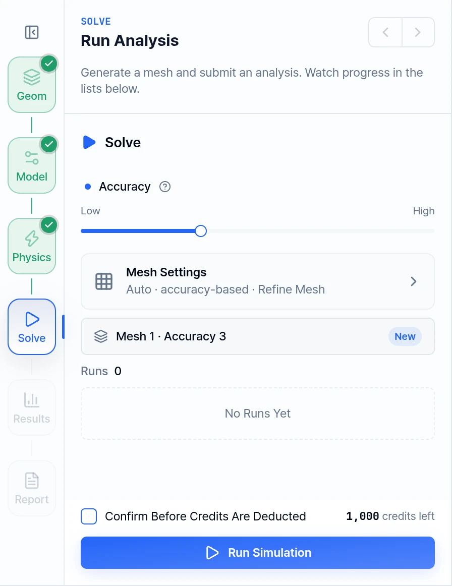
This figure shows the structural Solve panel before a run. Structural runs have no acceleration setting, so Accuracy is the only slider here.
Once Geom, Model and Physics are complete, click Run Simulation to start the structural calculation using the wing geometry, assigned material, constraints, loads, and mesh.
After the simulation finishes, review the generated results to evaluate whether the wing can withstand the assigned constraints and loads.
7. Results
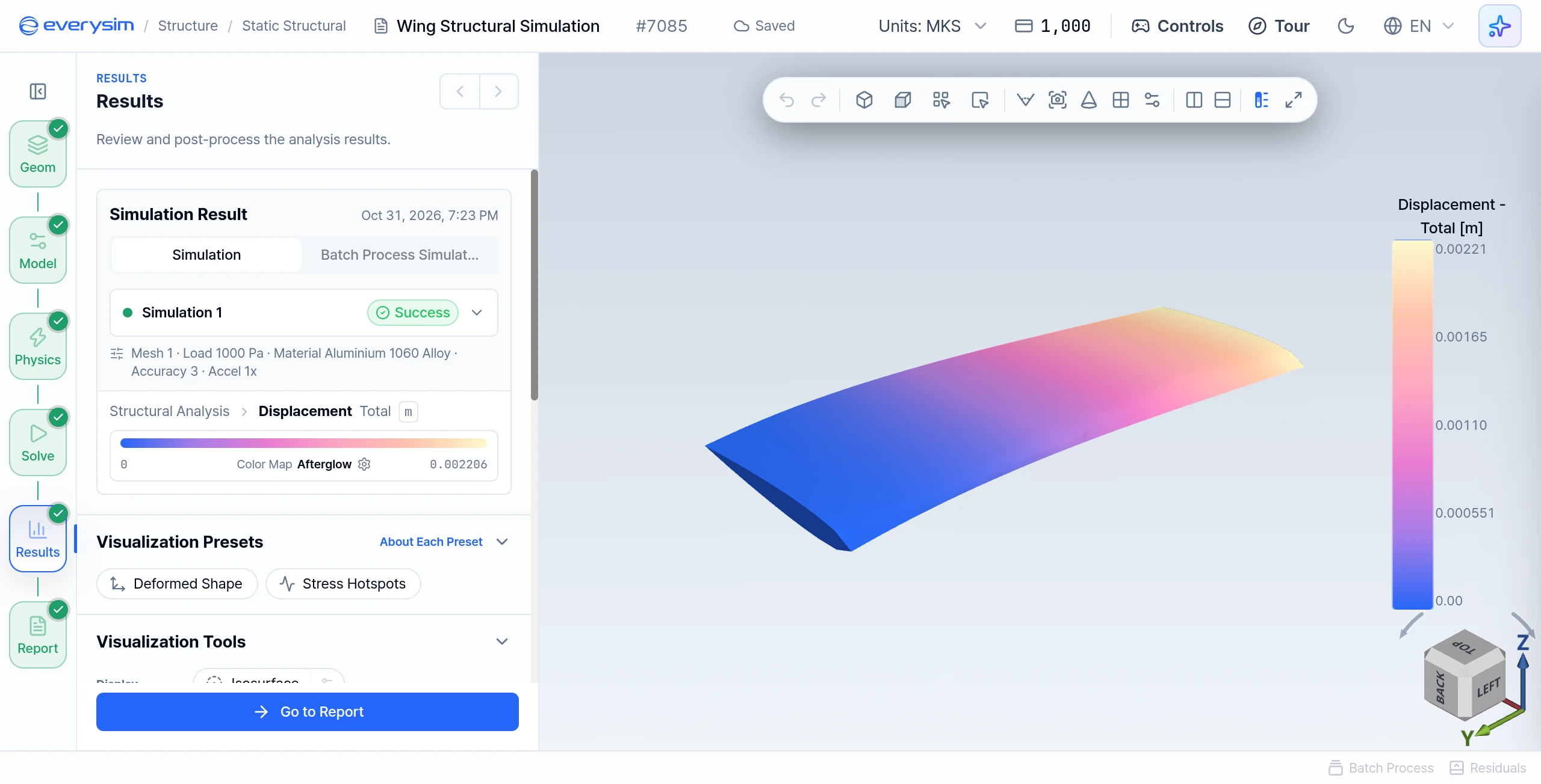
The Results stage displays displacement and stress fields on the wing. Expand Structural Analysis to inspect total displacement, axis components, equivalent stress, principal stress, and the stress tensor. The displacement legend shows the range and units for the selected result.
Use Scale Factor and Play Animation to understand the bending direction, but distinguish visualization scaling from physical displacement. For a typical cantilever-style wing setup, verify that displacement is lowest near the constrained root and increases toward the free span.
8. Report
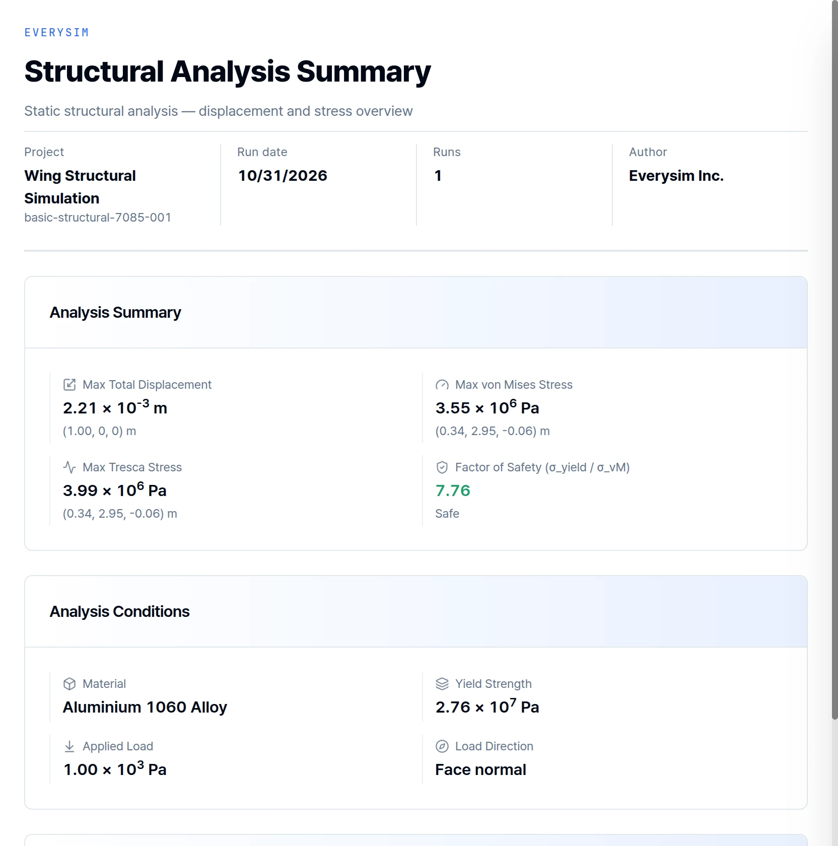
The report presents Max Total Displacement, Max von Mises Stress, Max Tresca Stress, Factor of Safety, Analysis Conditions, Engineering Insights and Key Results. A Factor of Safety below 1 means the peak von Mises stress exceeds the yield strength, and the report marks this as Yields. The Key Results charts compare displacement components and principal stresses at the critical node.
Before accepting the report, confirm that the constrained face represents the real attachment, the pressure direction matches the intended aerodynamic loading, and the mesh resolves the wing root and other stress-concentration regions.
Need Assistance or Have Questions?
Frequently Asked Questions: FAQ Link
Support Inquiries: support@everysim.io