Advanced Simulation Overview
Advanced Simulation provides more reliable and meaningful results through engineering simulation technologies (CAE), including Structural Analysis (FEA), Fluid Dynamics (CFD) and Rapid Aerodynamics.
1. New Project
To begin using Advanced Simulation for the first time, go to New Project and follow the steps below to set up your analysis.
Above the steps, choose Quick Start to load a recent configuration, or Manual to configure the analysis yourself. If you have no recent configuration, the dialog starts in Manual.
1.0. Domain Type
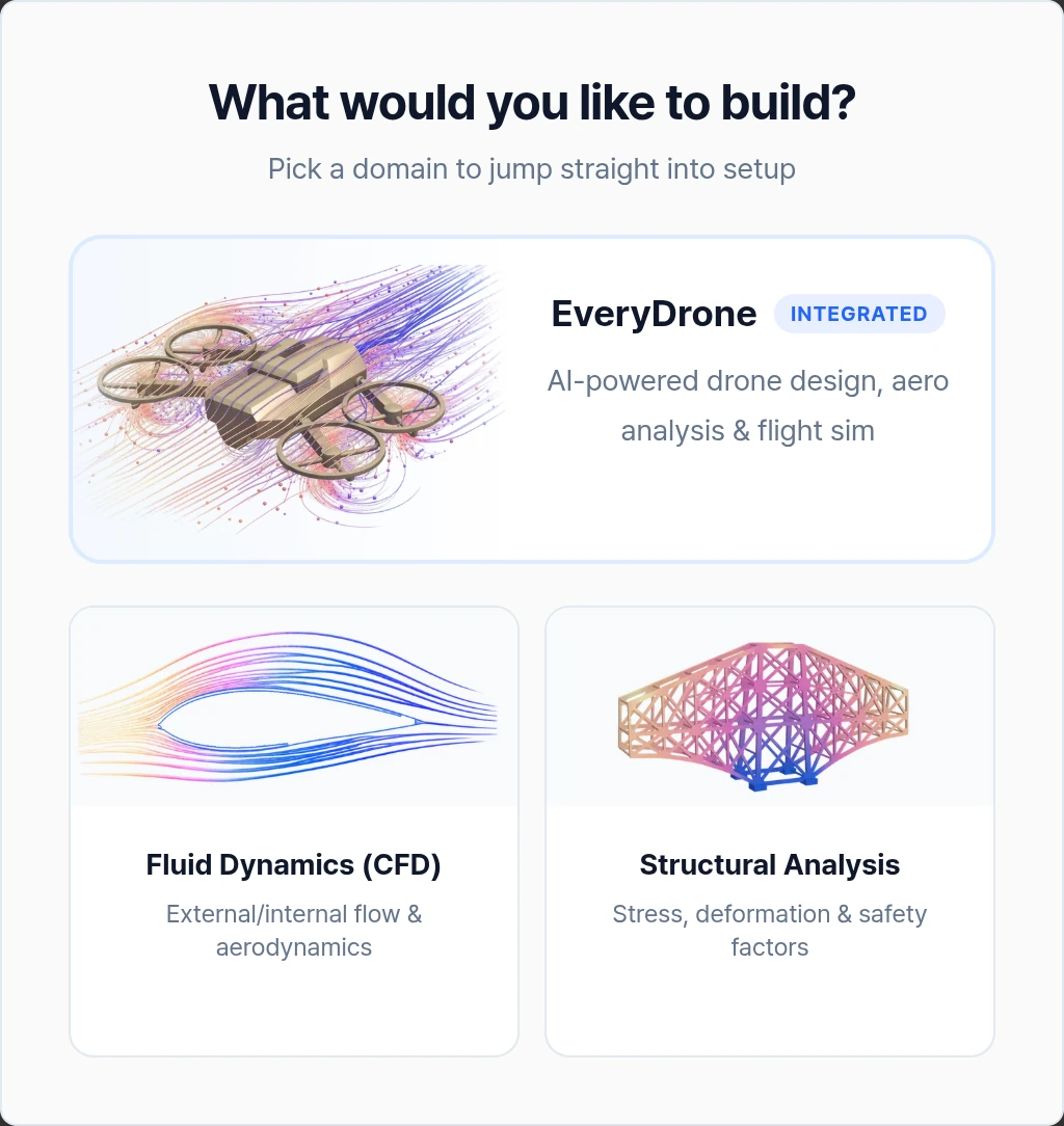
The dialog asks What would you like to build? Select the domain of your analysis. If a domain is already selected on the dashboard, this step is skipped and the dialog opens on that domain's setup.
- EveryDrone AI-powered drone design, aero analysis and flight simulation.
- Fluid Dynamics (CFD) External/internal flow and aerodynamics.
- Structural Analysis Stress, deformation, and factor of safety.
The next steps depend on the domain you choose:
- EveryDrone: Simulation Type > Testing Scope > Select Part, described in sections 1.1 to 1.3.
- Fluid Dynamics (CFD): Flow Type (External Flow; Internal Flow is shown but not available yet) > Select Part (Rotating Body, Wing, Stationary Body).
- Structural Analysis: Analysis Type (Static Structural Analysis, Modal Analysis, Transient Structural Analysis).
Running on your own CAD? For a fluid simulation, choose Fluid Dynamics (CFD) > External Flow > Stationary Body, or EveryDrone > Fluid Dynamics > Integration Testing. See Fluid Simulation on Your CAD.
1.1. Simulation Type
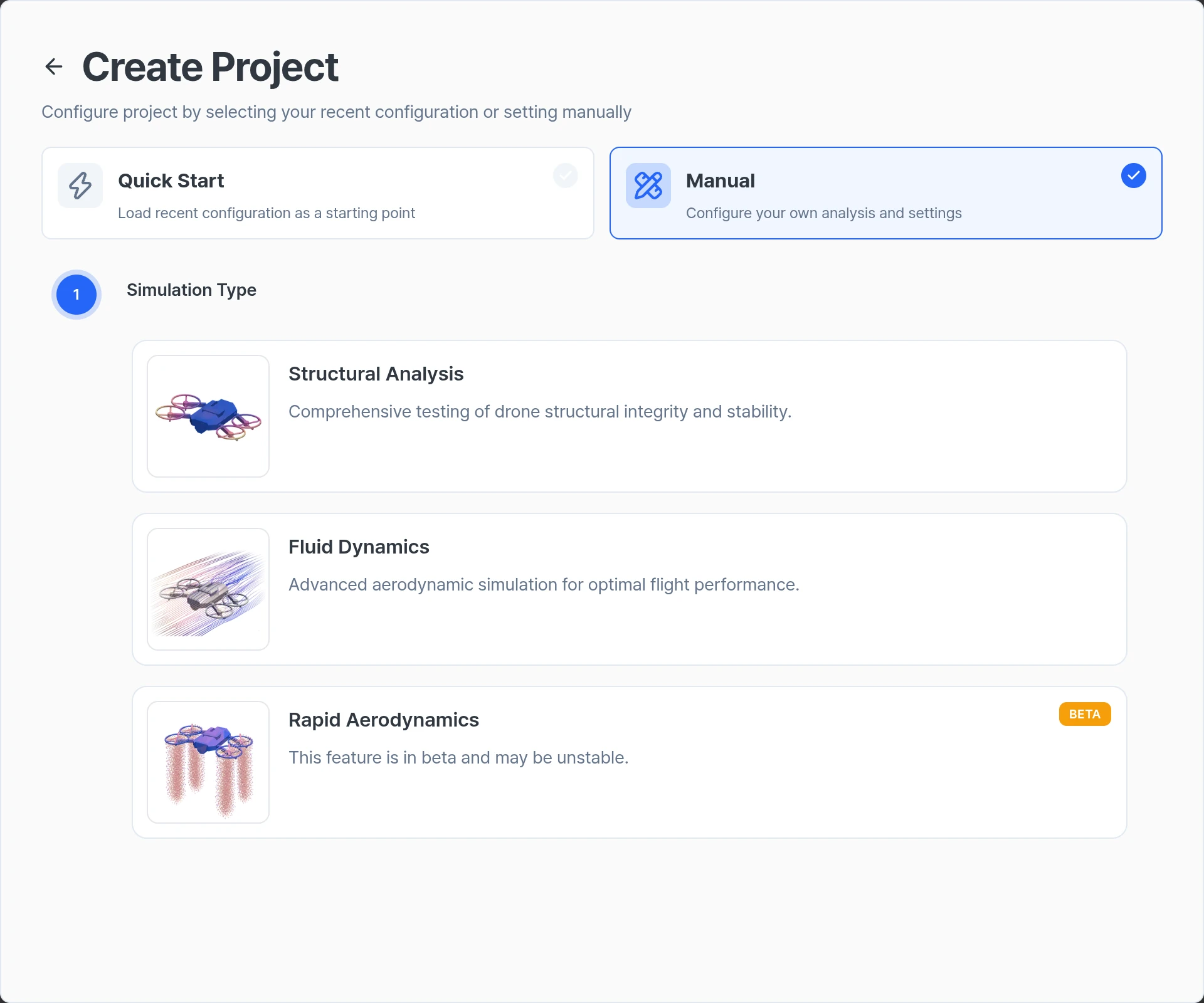
On the EveryDrone path, select the type of simulation to run:
- Structural Analysis
Generates a mesh for 3D structures and analyzes stress distribution and deformation under static load conditions. Modal and transient analysis are available from the Structural Analysis domain. Accepts STEP, STP, IGES, IGS, BREP and STL files, and multi-part CAD can be merged on import. - Fluid Dynamics
Generates a mesh for 3D fluid domains and evaluates aerodynamic characteristics using a Reynolds Averaged Navier-Stokes (RANS) equation-based solver. When importing CAD, supports STEP, STP, IGES, IGS, BREP and STL files. - Rapid Aerodynamics
Evaluates aerodynamic characteristics using a Vortex Method solver on surface meshes for unsteady conditions. When importing CAD, uses stl file format, and the stl file cannot exceed 4,000 surfaces. The workbench and reports call this module Vortex.
The Rapid Aerodynamics card carries a Beta badge: the feature is in beta and may be unstable.
1.2. Testing Scope
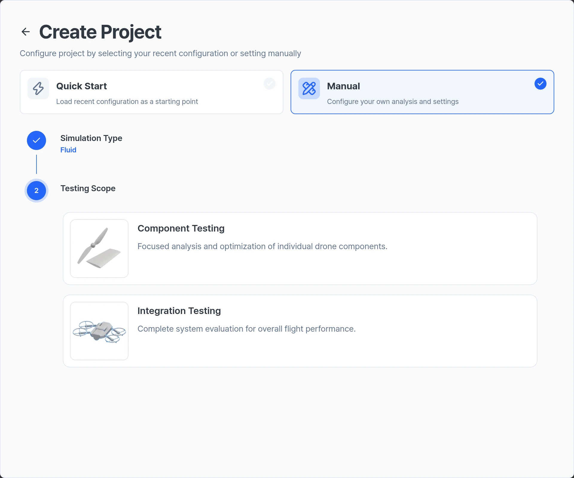
Select the test level:
- Component Testing
Provides services tailored for analyzing single components such as propellers and wings. - Integration Testing
Provides integrated or complex analysis services.
1.3. Select Part
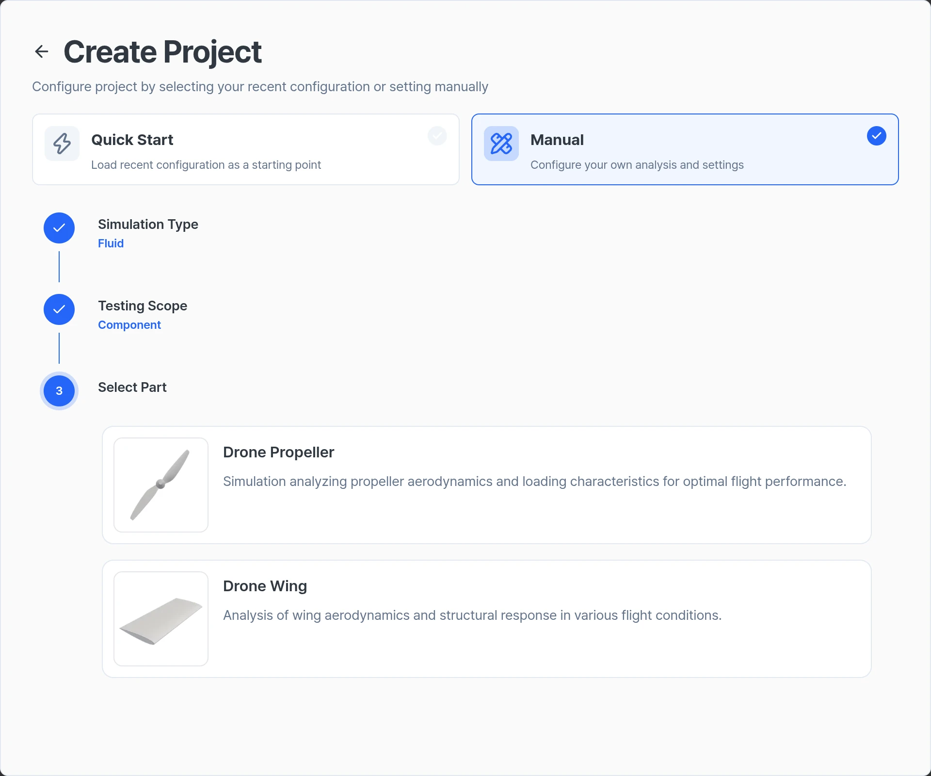
Component Testing
- Drone Propeller, Drone Wing: Focuses on evaluating the performance of components based on geometry, material selection, and aerodynamic characteristics.
Availability note: Rapid Aerodynamics currently supports the propeller component workflow. Component-wing simulation is not available in the current system.
Integration Testing
For Fluid Dynamics and Structural Analysis, no part selection is needed: the project runs on the geometry you provide. For Rapid Aerodynamics, choose Body-Only Mode or Propeller-Driven Mode.
1.4. New Project Name and Description
Finally, review the auto-filled project title and description, edit them if needed, and click Launch.
After launching, the Workbench guides the setup for your analysis type, such as materials and boundary conditions for structural, or the fluid domain and flow conditions for fluid.
1.5. Start from an Example
To see a full case before preparing your own model, open Example Simulations on the Geom step. An example loads the model, applies the setup and takes you to Solve, so you can run it right away. Which examples appear depends on the analysis type:
| Analysis | Examples |
|---|---|
| External flow | Flow Around a Fuselage, Flow Over a Sphere |
| Rotating flow | Static Thrust of a Propeller, Propeller in Forward Flight |
| Static structural | Tensile Test, Stress Around a Hole |
| Modal | Free Vibration of a Plate, Natural Frequencies of a Cantilever |
| Transient structural | Force Pulse on a Control Arm, Impulse on a Shaft Bracket |
| Rapid Aerodynamics | Propeller in Hover, Flow Around a Fuselage, Fuselage With a Propeller |
2. Workbench
When a project is created or opened, the Workbench screen is displayed. It runs in your browser, including Safari, and centers the simulation workflow around guided stages, a live setup panel, a large 3D viewport, shortcut actions, project status, result tools, and a reusable tour.
The examples below show the workbench tour. Available stages and fields may differ depending on the selected analysis type, but the layout and navigation pattern are shared across Advanced Simulation workflows.
2.1. Workflow Steps
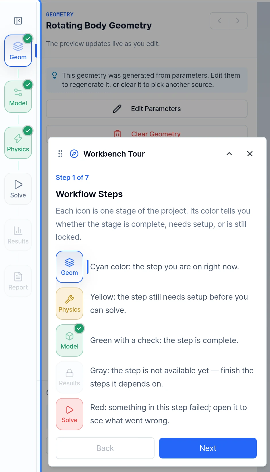
The left step rail shows the project workflow from setup to results. Each icon represents one stage of the project, such as Geom (Geometry), Model, Physics, Solve, Results, and Report.
- Cyan: The step you are currently editing.
- Yellow: The step still needs setup before you can continue.
- Green with a check: The step is complete.
- Gray: The step is not available yet because an earlier dependency is not finished.
- Red: Something in the step failed and needs review.
Use the step rail to understand where you are in the workflow and what must be completed before solving.
2.2. Setup Panel
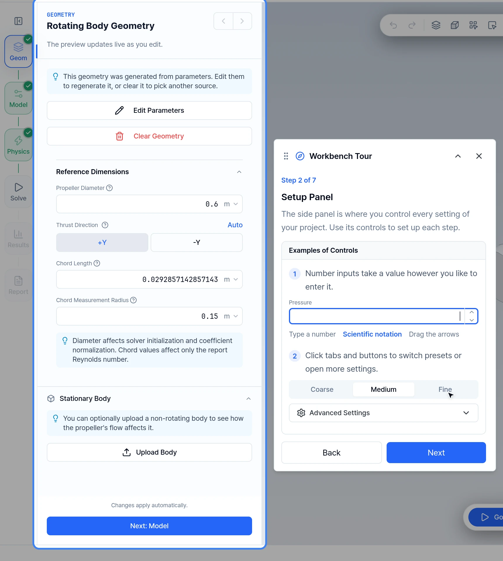
The setup panel contains the controls for the active stage. Use it to import or generate geometry, edit parametric values, configure model settings, define physics options, and run solver setup.
- The panel title and subtitle explain the active stage.
- Completed items show a check mark in the panel.
- On structural projects, forces, displacements and materials can be set for several faces or parts at once.
- Numeric inputs accept typed values, scientific notation, or dragging the arrows beside the field.
- The Before run chip in the status bar lists the requirements still missing. Structural problems also show a checklist in the panel.
- The panel can include stage-specific controls, such as the Flow Type choice between Box Flow and Rotating Flow on stationary-body and integration fluid projects.
Changes apply to the live preview as you configure the active stage.
2.3. 3D Viewport
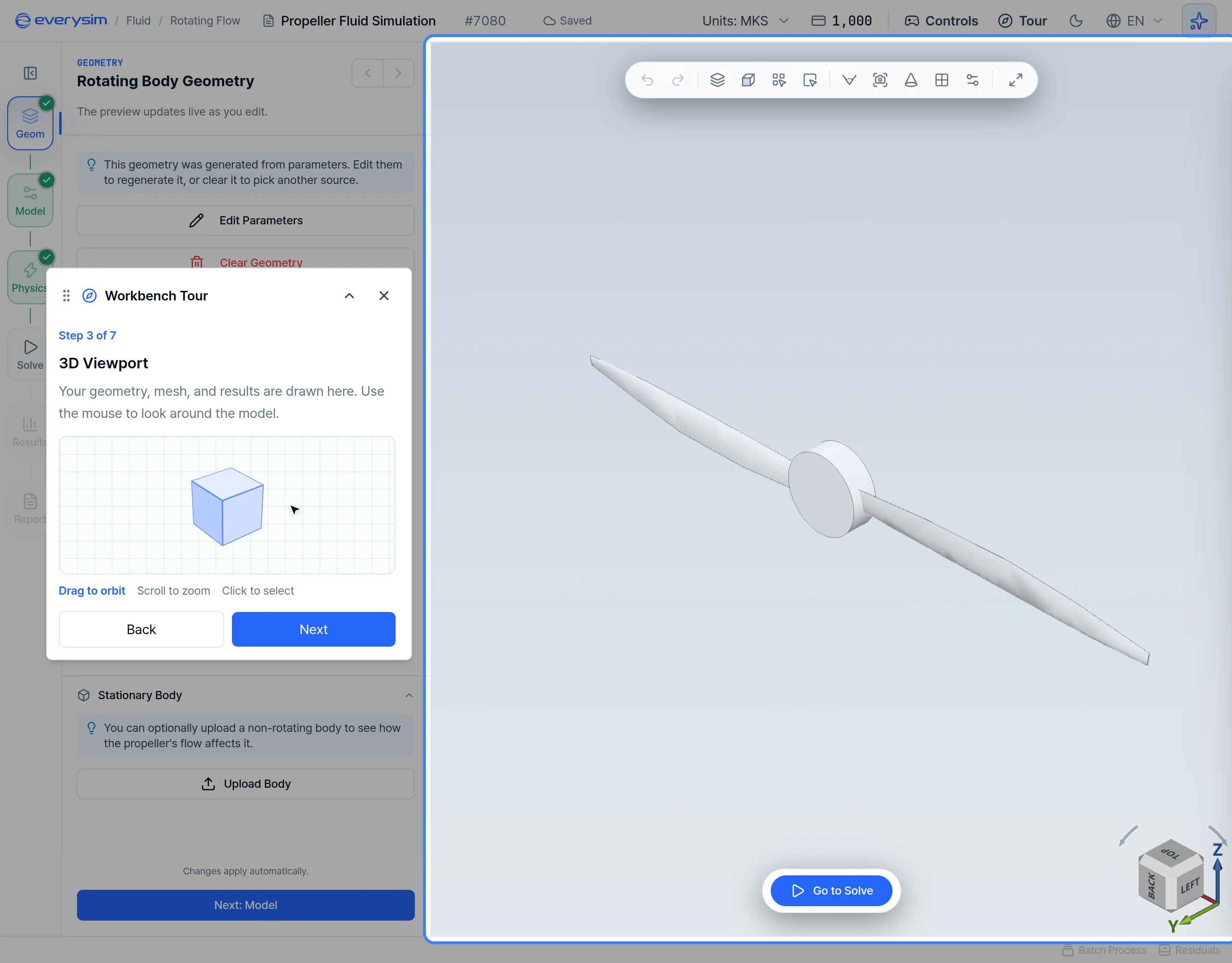
The 3D viewport is the main workspace for geometry, mesh, setup previews, and results.
- Drag to orbit the scene, scroll to zoom, and click objects to select them when selection is enabled.
- Review geometry and setup changes directly on the canvas.
- Use the view cube to confirm orientation or return to standard views such as Top or Front. Its arrow buttons rotate the view in 90° steps. On a Mac, ⌘+drag also rotates the view.
- When result data is loaded, use the viewer toolbar to change display modes and capture the view.
2.4. Shortcut Bar
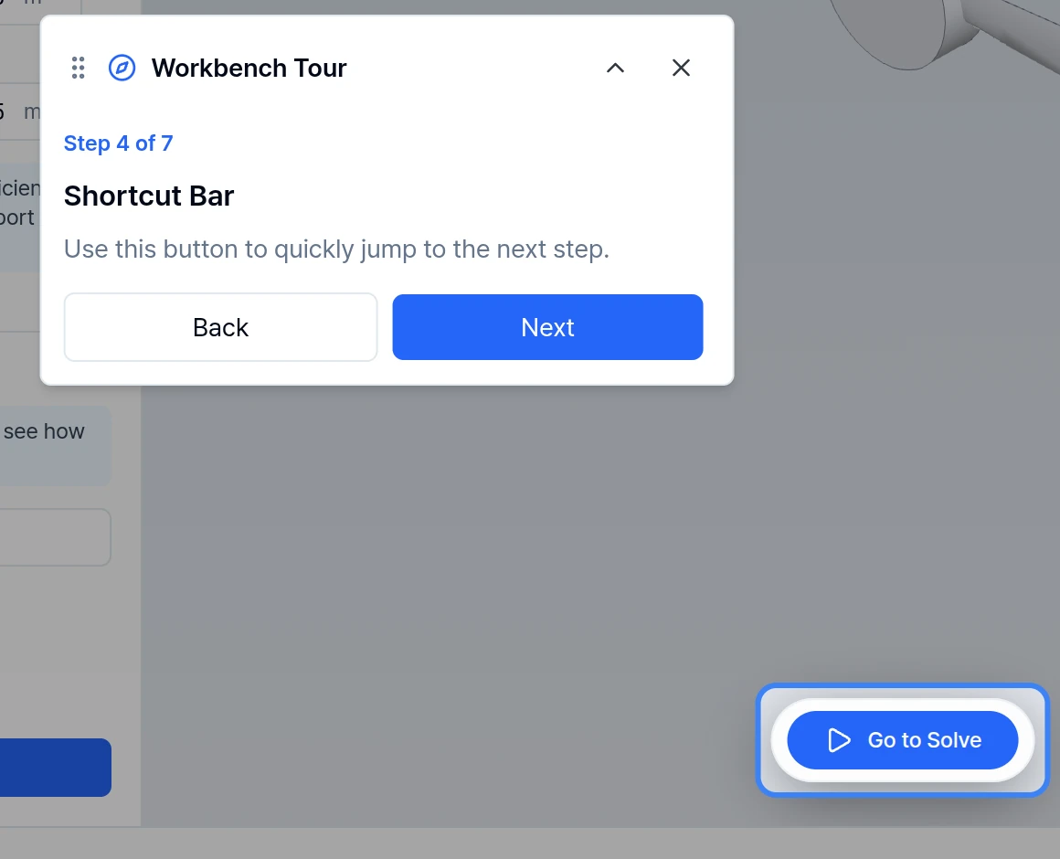
The shortcut bar appears near the bottom of the viewport and provides the next main action for the current workflow stage.
- The button label changes with the active stage, such as Next: Model, Set Up Fluid Domain, Go to Solve, or Run Simulation.
- Use this button when the setup panel indicates the current stage is ready.
- The shortcut keeps common next-step actions available even while you are focused on the 3D viewport.
2.5. Status Bar
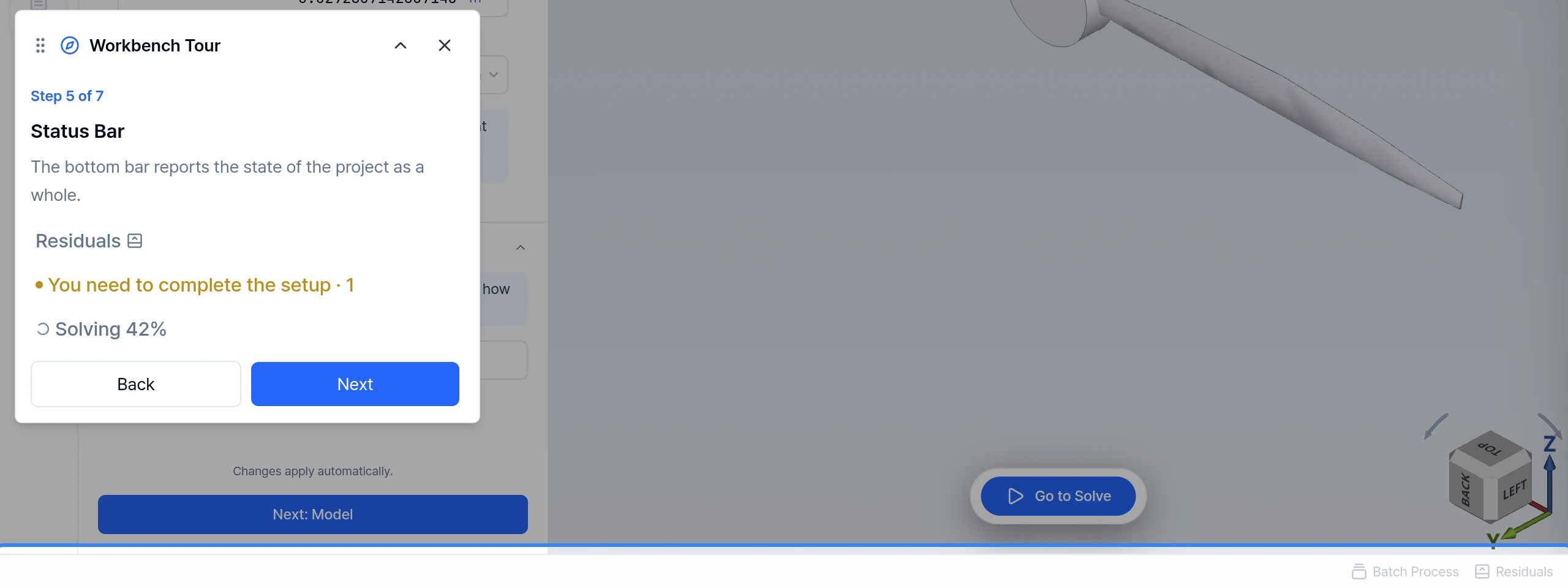
The status bar at the bottom of the workbench reports the state of the project as a whole.
- Before a run, it shows whether setup is complete or which required setup is still missing.
- During solving, it shows solver progress such as Solve iteration 687/1000.
- When residual data is available, the status bar can provide access to residual information.
- Use this bar for a quick readiness and progress check without leaving the current stage.
2.6. Job Panel
The Job Panel in the Solve step is where you start a run and follow its progress.
- Run the simulation from here and watch meshing and solving progress live.
- Every finished run stays listed, so you can reopen an older result at any time.
- To sweep several condition values in one go, see Batch Simulation.
When a Run Fails
A failed run is classified by cause (for example Failed, Not Converged or Needs Review), with a recommendation and buttons for the next step:
- Fix in a named step: Jumps to the step that needs fixing.
- Raise Accuracy to a named level: Raises the mesh accuracy for the next run.
- Retry: Runs it again.
Diverging CFD runs are detected and stopped early. You can also ask the AI Assistant (section 2.10) to explain a failed simulation.
2.7. Result Tools
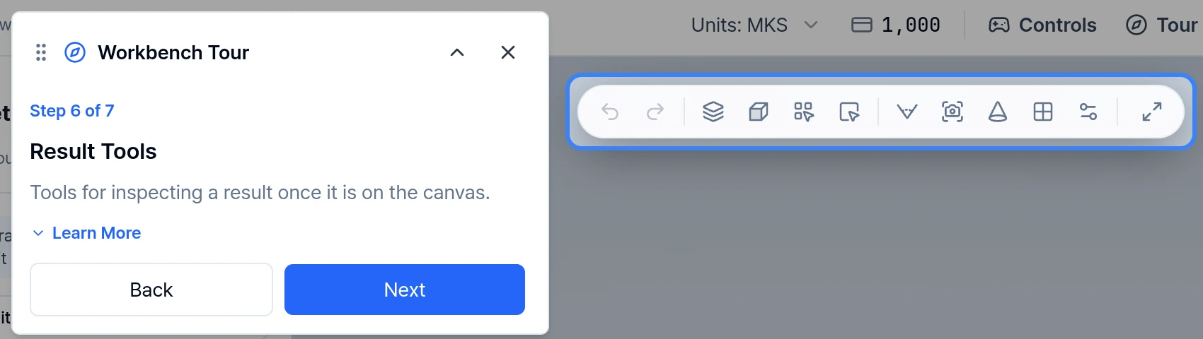
The Results panel holds the tools for inspecting a result.
- Results Tree: Expand the tree and pick a field to display it on the geometry. Switching fields recolors the model without re-running the simulation.
- Visualization Presets: Common readings, each set up in one click. Click an applied preset again to put the view back.
- Visualization Tools: The post-processing tools, including Color Map, Threshold, Isosurface, Streamline, Probe, Cut (Section Slice) and Clip (Cutaway View). Flip a tool's switch to apply it and open its controls beside the panel.
The viewer toolbar above the canvas provides common actions such as display mode, camera views, screenshot capture, split views, and fit view.
2.8. Tour Button
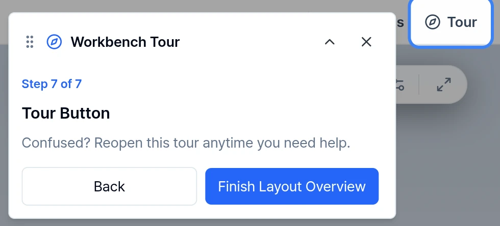
The Tour button in the top bar opens the Workbench Tour dialog whenever you need help with the layout.
- Choose Start Overview to walk through the parts of the workbench currently on screen.
- Choose Browse Tutorials to learn by setting up and running a full project.
2.9. Canvas Render Settings
Settings in the viewer opens Canvas Render Settings, which control how the model looks on the canvas. They are useful for reviews and presentations.
- Style: CAD, Neutral, Realistic, Photo Studio, Hangar, Open Sky, Clay or Cartoon. Each style changes the lighting, reflections and edge lines.
- Skin: A surface pattern or finish. It doesn't change colors or materials already set in the CAD file.
- Lighting: Where the main light comes from.
- Background: The color or gradient behind the model.
- Floor: Grid, Road, Glass or None, drawn under the model in the flow preview.
Your choice is kept for your next projects, and results stay in their plain view so they read accurately.
2.10. AI Assistant
The AI Assistant opens in the panel on the right of the workbench. Your plan determines whether it is available. Ask it about your setup or results in plain language. It can change settings, build and edit parts, run simulations and explain failed simulations.
- Before a run, it asks you to Approve or Reject, and Run Settings lets you adjust Simulation Acceleration and Mesh Accuracy first.
- Changes appear as tool cards in the conversation, and Revert takes one back.
3. Link to Detailed Design Settings
Access the following link to review the information required to perform your desired analysis.
3.1. Structural Analysis (FEA)
Component
Your Own CAD
3.2. Fluid Dynamics (CFD)
Component
Your Own CAD
3.3. Rapid Aerodynamics
Component
Integration
3.4. Batch Simulation and AI Report
Need Assistance or Have Questions?
Frequently Asked Questions: FAQ Link
Support Inquiries: support@everysim.io