4.7 Rapid Aerodynamics: Component-Propeller
A Rapid Aerodynamics propeller project opens on the Model step and moves through Physics, Solve, Results and Report. There is no geometry upload or mesh step.
1. Model: Create Propeller
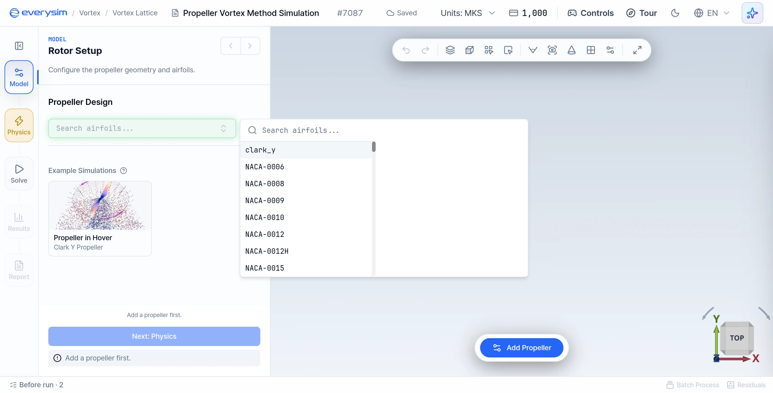
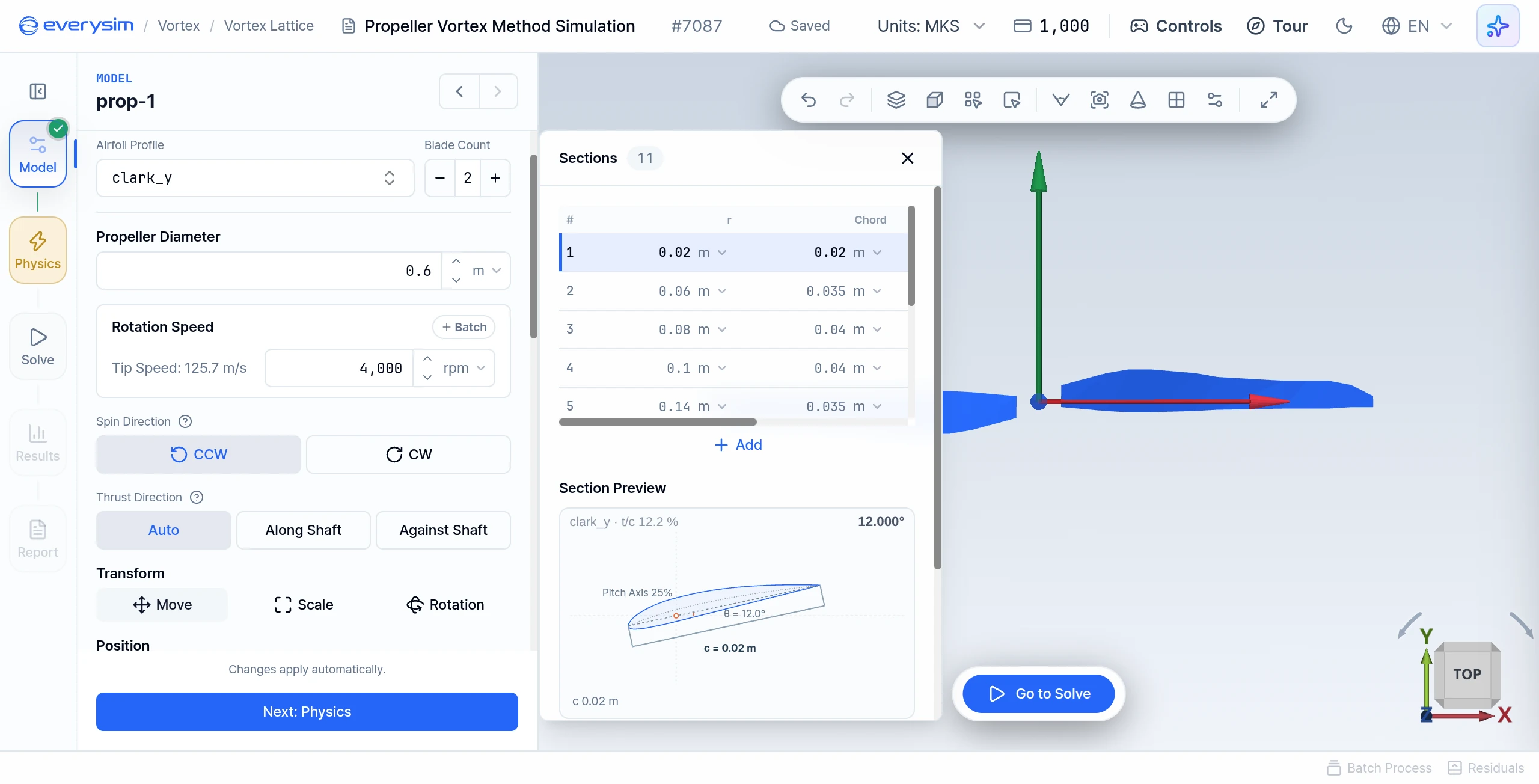
Multiple propellers can be created and configured individually. The configuration process is as follows:
1.1. Add Propellers
In the Propeller Design panel, search for an airfoil and select it, then click + (Add Propeller). The button stays disabled until an airfoil is selected, and the selected airfoil serves as the basis for the propeller geometry.
Each click adds one propeller, named prop-1, prop-2 and so on, to the Propeller List. Click a row to open its settings. At least one propeller is required: until then, the next step is blocked with the message Add a propeller first.
From the list you can also rename, duplicate or delete a propeller. Select Multiple lets you edit several propellers together in Selected Propeller Settings.
1.2. Blade Configuration
- Airfoil Profile: Changes the propeller's airfoil.
- Blade Count: Sets the number of blades on the propeller (minimum 1, default 2).
- Propeller Diameter: Sets the diameter and scales every section with it.
- Distribution: Edit the blade by dragging the planform charts. With Proportional on, dragging a value also changes the adjacent points. Reset restores the default distribution.
- Sections: Opens the section table, where you set the radius, chord, twist and pitch axis of each section. Add or remove rows here; a blade has 2 to 200 sections.
1.3. Rotation Speed
- Rotation Speed: Sets the propeller speed (default 4000 RPM). The tip speed is shown beside the field. The maximum depends on the diameter, because the tip speed must stay at or below Mach 0.7.
- Batch: Enter several speeds to solve one case per speed. All propellers run at each speed together.
1.4. Spin and Thrust Direction
- Spin Direction: Select CCW (default) or CW, as seen with the shaft pointing at you. CW builds the mirror-image blade, so thrust stays the same and the turning moment on the aircraft reverses.
- Thrust Direction: Select Auto, Along Shaft or Against Shaft. Thrust along this direction reads as positive in the report. Auto follows the inflow until you set it.
1.5. Position and Rotation Configuration
- Transform: Move, Scale and Rotation show gizmos on the canvas.
- Position: Sets the position of the propeller center as
<X, Y, Z>. - Rotation: X and Y tilt the propeller's axis. Propeller sets the initial rotation angle around the propeller center.
2. Physics: Flow Settings
In the Physics / Model panel, set the inflow under Flow Settings, then click Next: Solve.
- Direction: Specifies the direction of flow: X Axis (default), Y Axis, Z Axis or their negative directions. The direction is shown as a green arrow on the canvas.
- Wind Speed: Sets the flow speed, in the unit of the project's unit system. The default is 0, and a speed of 0 is treated as hovering. The combined speed,
sqrt(tip speed² + flow speed²), must not exceed Mach 0.7 (240.1 m/s). The panel shows the combined speed, and exceeding the limit blocks the run.
To solve several speeds as one batch, use Batch on the Wind Speed field.
3. Solve: Run Simulation
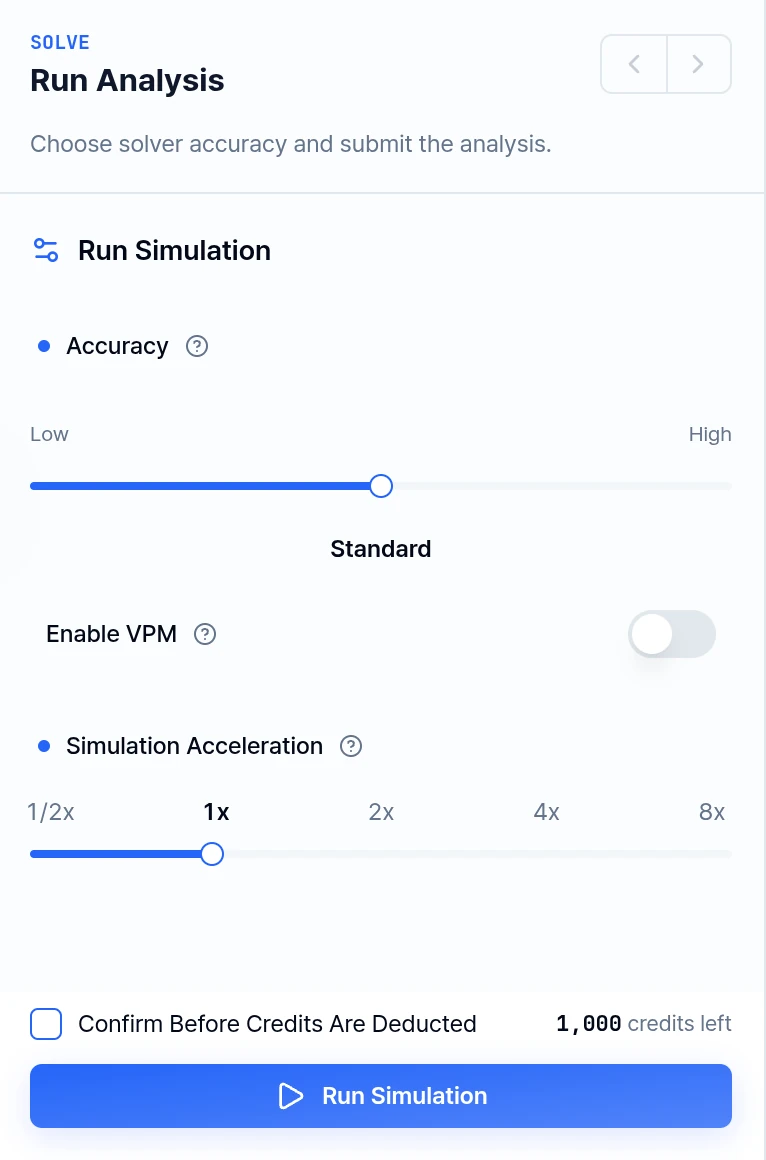
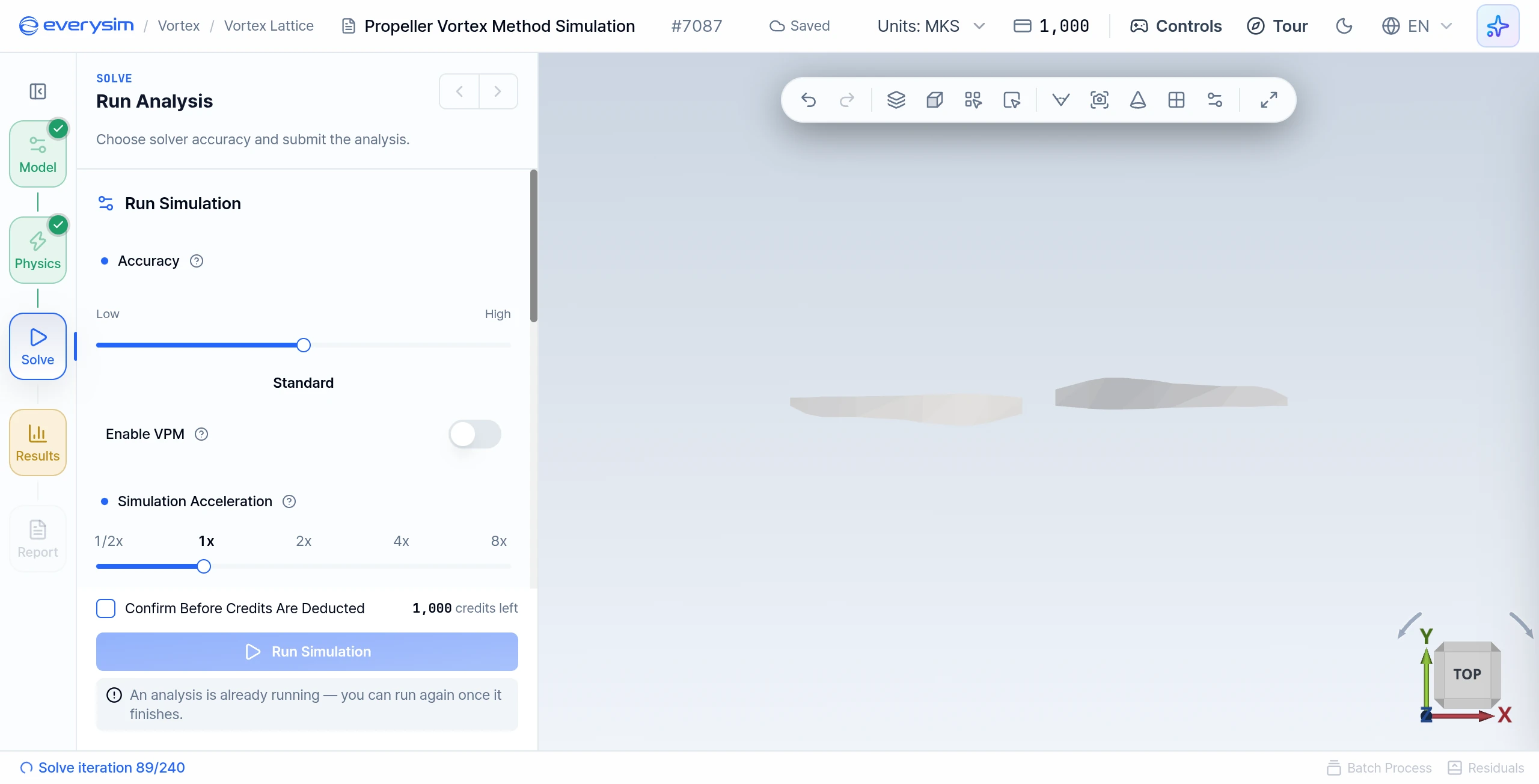
In the Run Analysis panel, set the solver options and start the analysis.
- Accuracy: Drag the slider from Low to High to select Fast, Standard (default) or Accurate. Higher accuracy gives more precise results but takes longer and uses more credits.
- Enable VPM: Turns the Vortex Particle Method on or off (default off). At Fast, VPM is off and cannot be enabled. Accumulating many particles can increase computation time and memory use.
- Simulation Acceleration: Select 1/2x, 1x, 2x, 4x or 8x. Higher acceleration uses more resources and consumes credits faster, while 1/2x uses fewer credits but can be much slower. The available stops depend on your plan's core limit.
Click Run Simulation to start the analysis. Credits are deducted for the run. Select Confirm Before Credits Are Deducted to review the charge first.
4. Results
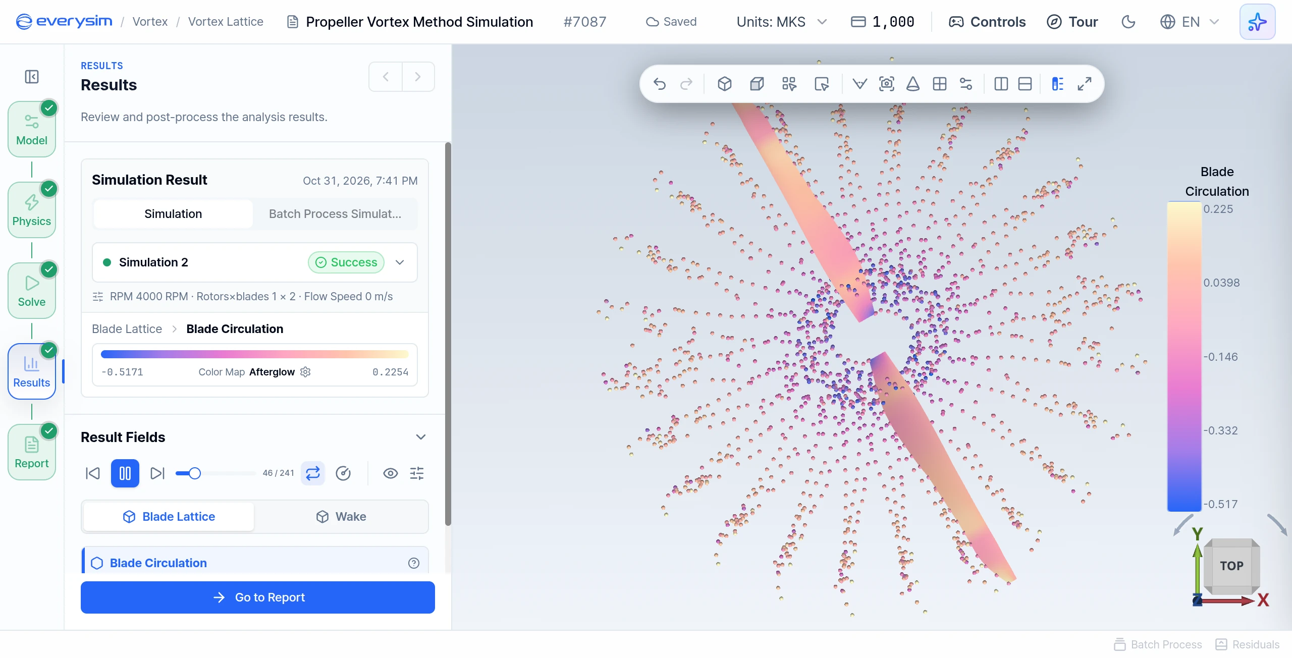
In the Results step, choose a part and a field to display as a 3D contour:
- Blade Lattice: Blade Circulation or Blade Pressure Coefficient
- Wake: Wake Circulation
- Vortex Particles: Particle display, with no selectable field
Use the playback bar to step through the run and Color Map to adjust the contour colors.
5. Report
This section allows you to evaluate propeller performance based on numerical data derived from simulation results.
5.1. System Force and Moment Distribution (Time History)
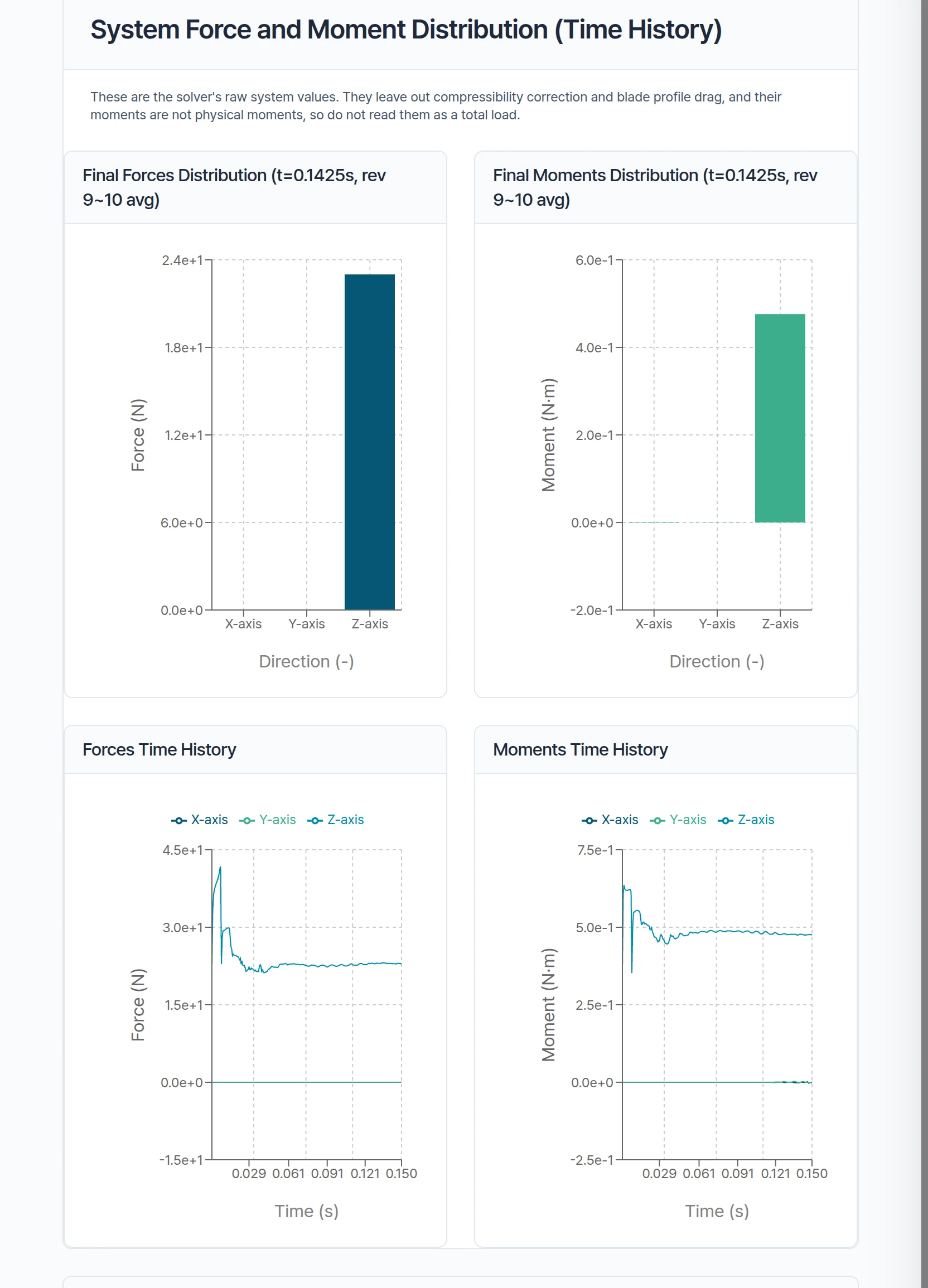
- Shows the final values and time history of the three force and three moment components.
- If the report marks them as the solver's raw system values, do not read them as a total load.
- Runs that record full load vectors show Rotor and Body Loads and Combined Rotor and Body Loads (Time History) instead.
5.2. Core Performance Metrics
Displays aerodynamic performance for each propeller. Choose the propeller under Select Propeller, and the equations under Calculation Mode: Propeller (Thrust-Focused) or Rotor (Hovering). The coefficients are defined as follows:
- Thrust Coefficient: Dimensionless thrust generated by the propeller
- Torque Coefficient: Dimensionless torque required for propeller rotation
- Power Coefficient: Performance indicator of the power required for propeller rotation in dimensionless form
5.3. Performance Summary
Lists thrust, shaft torque and shaft power together with the operating conditions. Performance for This Inflow depends on the inflow:
- Figure of Merit: Hover efficiency, shown only for hover runs. It should be between 0 and 1; if it is not, the report warns you to review the simulation settings.
- Advance Ratio (J) and Propulsive Efficiency: Shown for runs with axial inflow.
Propeller Forces & Coeffs charts these values below the summary.
Sectional Load Distribution
Graphically displays the thrust and torque distribution acting on each section of the propeller blade.
Need Assistance or Have Questions?
Frequently Asked Questions: FAQ Link
Support Inquiries: support@everysim.io