4.3 Structural Analysis: Your Own CAD
The Propeller and Wing pages explain how to generate a part and analyze it. This page covers the other path: running a structural simulation on your own CAD, from upload through to the report.
Start from a structural project. In EveryDrone, choose Structural Analysis, then Integration Testing. Project setup offers no Aircraft or Custom choice: there is one workflow for any uploaded model. The figures on this page show the Bracket sample model, so you can follow along without a CAD file of your own.
1. Upload CAD
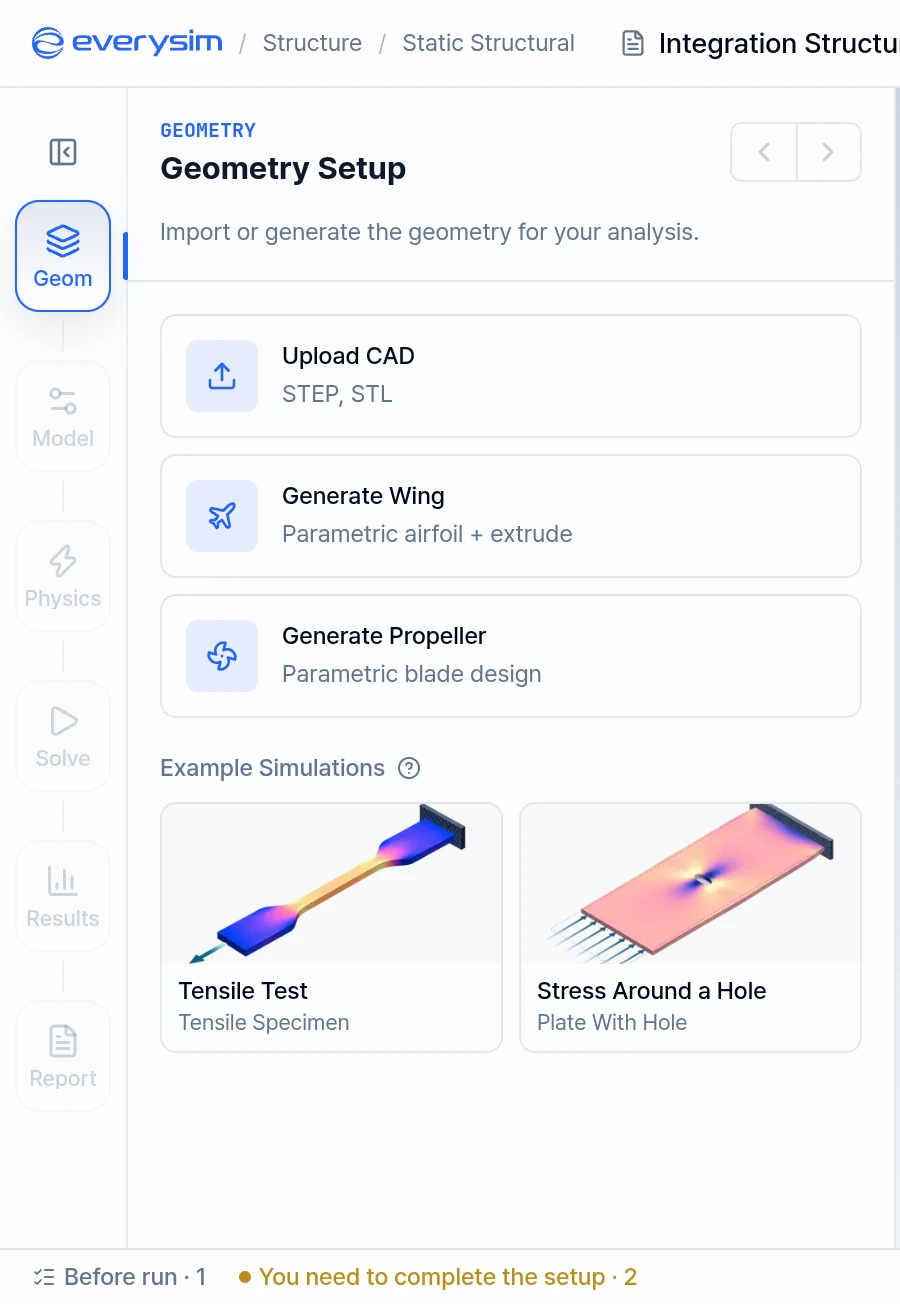
The Geom step opens on Geometry Setup. Click Upload CAD. You can also use Generate Wing or Generate Propeller here, and Example Simulations loads a preset case.
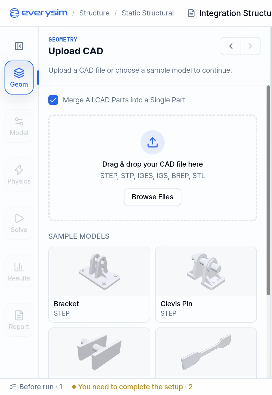
Drop a file on the upload area, click Browse Files, or pick one of the Sample Models.
1.1. File Formats
The upload accepts .step, .stp, .iges, .igs, .brep and .stl. The Upload CAD card reads "STEP, STL", but the upload view accepts all six. See the CAD Guidelines for preparing each format.
STL and BREP carry no unit information, so the app asks for the unit on import. STEP and IGES use the unit declared in the file unless you choose another. Check the unit carefully, because it sets the physical size of the model.
1.2. Sample Models
Sample Models offers Bracket, Clevis Pin, Two-plate shaft bracket, Tensile Specimen, Plate With Hole and Beam. Use one to try the workflow before uploading your own file.
1.3. Merge All CAD Parts into a Single Part
This option is on by default, and it decides how the parts of your model are treated:
- On: The model is analyzed as one body with one material, and contacts can't be set. If the parts don't touch, the merge fails. Close the gap in CAD, or import without merging.
- Off: Each part keeps its own body. Assign a material to every part, then connect the parts with Bonded Contact in Physics (see section 4.1).
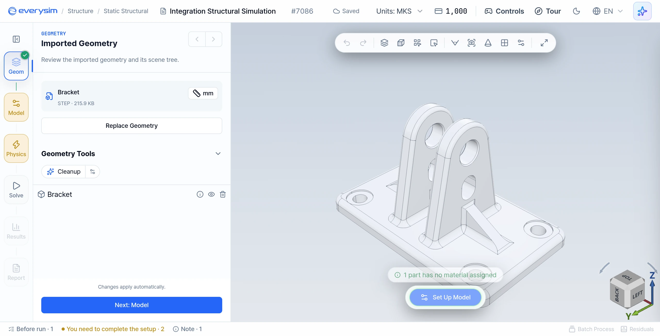
If the import is successful, the geometry appears in the viewport and the file is listed under Imported Geometry, with its parts in the tree below.
2. Geometry Health and Heal Geometry
The app inspects the geometry after import. When it finds a problem, the Geom step shows a health report with the affected parts:
- Blocking Defects: Resolve these before running.
- Warnings: These may affect result accuracy.
An STL lists Risk items instead: meshing or the simulation may fail. If it does, fix the geometry in CAD and export the STL again.
Click Heal Geometry to repair the geometry automatically. Repairing one defect can expose others it was masking, so the count may not reach zero in one pass and can even increase. Run healing again to resolve the remainder. For an STL, healing closes holes with flat patches, so check where a hole was closed if the shape matters there.
If Heal Geometry is not offered, automatic healing can't repair these issues. Fix the model in your CAD system and import it again. The same applies if the same defects persist after healing.
Structural analysis needs closed solids. A few messages you may see:
- Geometry with holes, or with faces that don't close, is read as a shell, and a shell can't take a material.
- An STL that is not a closed volume can't be meshed for a structural run.
- An IGES with pieces that don't close can't be simulated. The geometry check marks those pieces as Non-Solid Geometry.
Geometry Tools also offers Cleanup, which removes small regions that reduce analysis quality while preserving the shape.
When the geometry is ready, click Next: Model.
3. Model: Assign Material
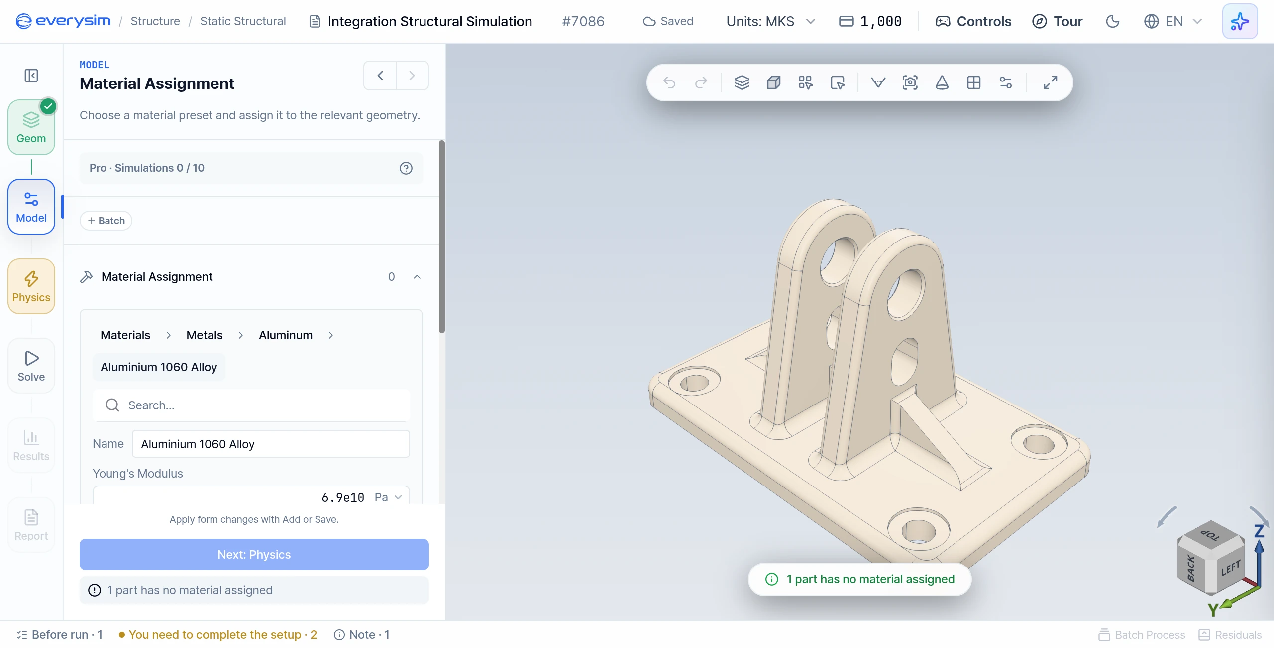
Click Add Material, then choose Materials > category > family > material, or use the search box. To define a custom material, choose the closest preset and edit its values.
Select the parts, then click Add. A merged model is one body, so it is selected automatically. On a multi-part model, click parts in the viewport or use Select Unassigned Elements. Every part needs a material before you can run.
4. Physics: Boundary Conditions
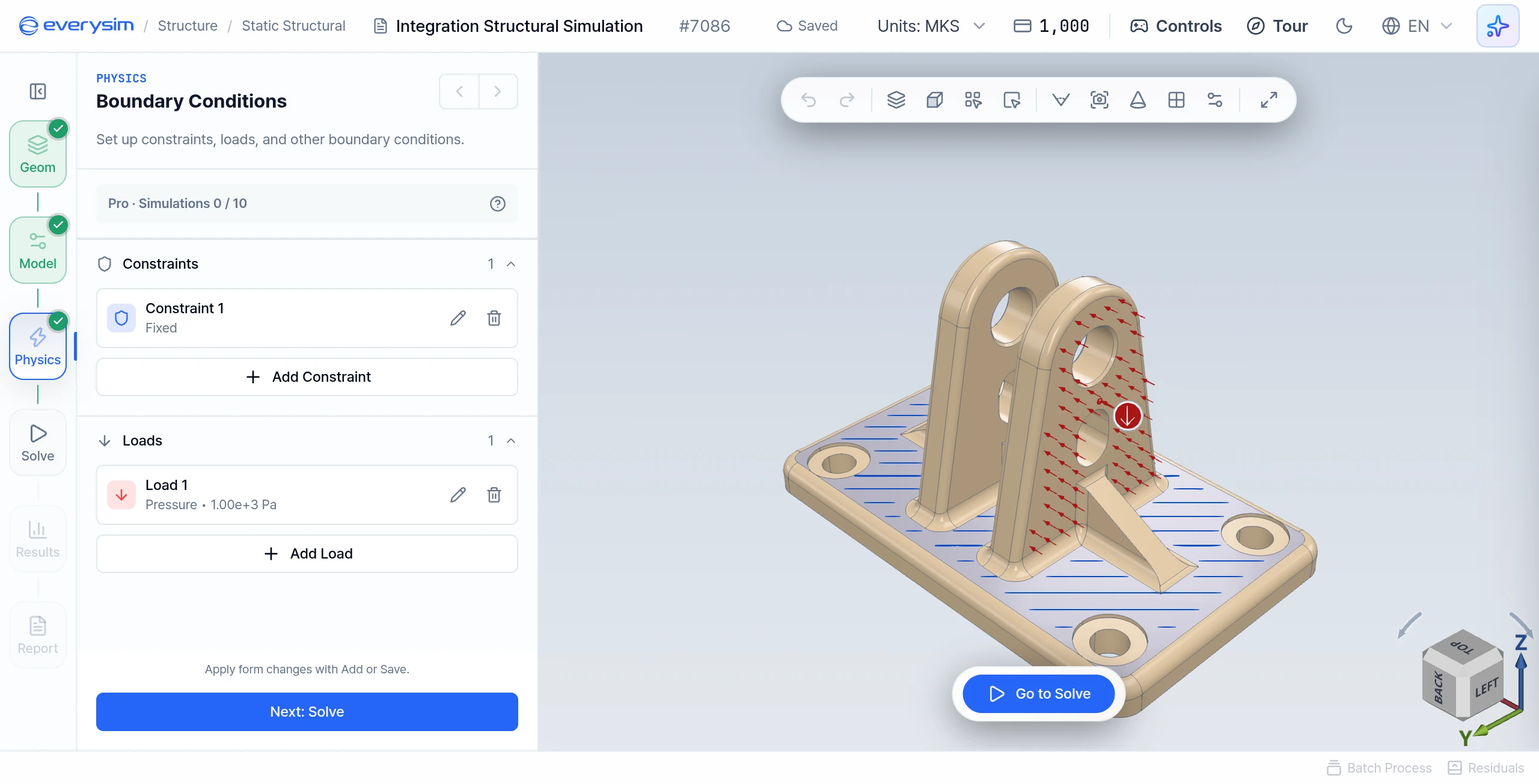
A run needs at least one constraint and one load.
4.1. Bonded Contact
This section applies when you uploaded the model without merging. Auto Apply detects touching parts and creates the contacts, and Add Contact lets you define one yourself. On a merged model, contacts are unavailable because it is analyzed as a single body.
4.2. Constraints
Under Constraints, click Add Constraint and set Type:
- Fixed: Locks the selected faces.
- Displacement: Applies a displacement to the selected faces. Enter Dx, Dy, Dz, or * to leave an axis free. At least one axis must be constrained.
Click faces in the viewport (hold Shift to add more), then click Add.
4.3. Loads
Under Loads, click Add Load and set Type:
- Pressure: Applies a force perpendicular to the selected faces. Enter the value in Magnitude.
- Facial Force: Applies a force in an arbitrary direction on the selected faces. Enter Fx, Fy, Fz.
- Gravity: Needs no face selection. A model can have only one.
- Displacement: Takes the same Dx, Dy, Dz input as the displacement constraint.
Click faces in the viewport (hold Shift to add more), enter the values, then click Add. Each value's unit is shown beside its field, and follows the active unit preset.
5. Solve: Mesh
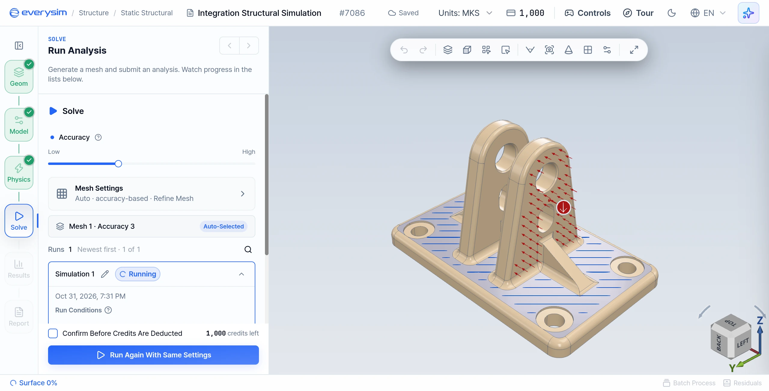
5.1. Accuracy
The Accuracy slider has 7 steps, from Low to High. Higher values create a finer mesh, and take longer and use more credits. Steps 1-2 may give large errors. The slider has no effect when Auto Size is off.
5.2. Mesh Settings
Click Mesh Settings to open these switches:
- Auto Size: Sizes follow the Accuracy slider. Turn it off to enter values manually.
- Refine Mesh: Slower, but produces a smoother mesh
- Feature Smoothing: Meshes across tiny or redundant CAD edges
- Detail Capture (Beta): Captures complex surfaces and small features more accurately
Turning off Auto Size shows the manual controls. The mesh is tetrahedral.
- Mesh Detail: Overall element size relative to your model
- Size Transition Smoothness: How gradually elements grow from small to large
- Shape Accuracy: How closely the mesh follows curved surfaces
- Edge Refinement: Maximum number of elements along a single edge
- Shape Accuracy Method: How curvature is measured (Standard, Adaptive, Precise, Maximum Precision)
- Element Shape: Planar or Curved
- Mesh Complexity: Standard or Complex
You don't have to generate the mesh yourself. Run Simulation generates the mesh or reuses a matching one, then solves. To inspect the mesh first, click Generate Mesh Only in Mesh Settings.
When meshing finishes, the Meshes list shows Success. Click the eye icon on the mesh card to view the mesh.
6. Solve: Run Simulation
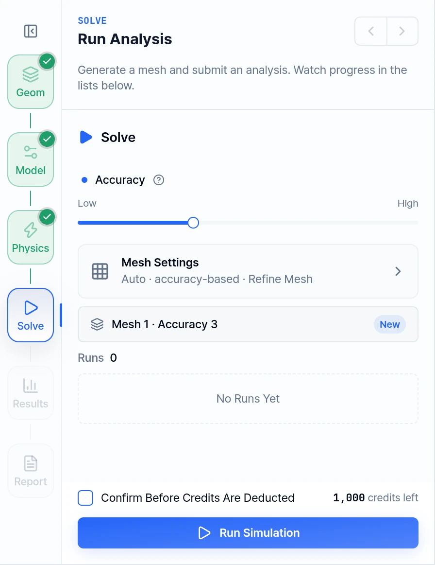
Structural runs have no acceleration setting. Higher Accuracy takes longer and uses more credits.
Click Run Simulation. The run appears in the Runs list and its status changes to Running.
7. Results
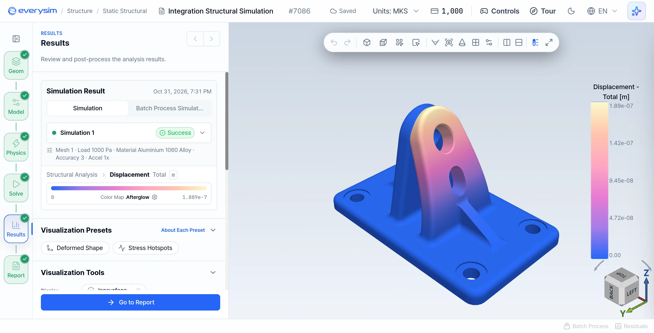
When the simulation completes, expand Structural Analysis in the Results step. Results are grouped under Displacement, Equivalent Stress, Principal Stress and Stress Tensor.
- Displacement: Total displacement and its X-, Y- and Z-axis components.
- Equivalent Stress: von Mises, Tresca (Max Shear) and Signed von Mises fields.
- von Mises: Assumes yielding occurs when the distortion energy (the deviatoric part of strain energy) reaches a critical value. Commonly used to predict the onset of yielding by comparing with the yield stress.
- Tresca: Assumes yielding occurs due to the maximum shear stress. Generally more conservative than von Mises.
- Principal Stress: σ₁, σ₂ and σ₃.
- Stress Tensor: The individual stress components.
8. Report
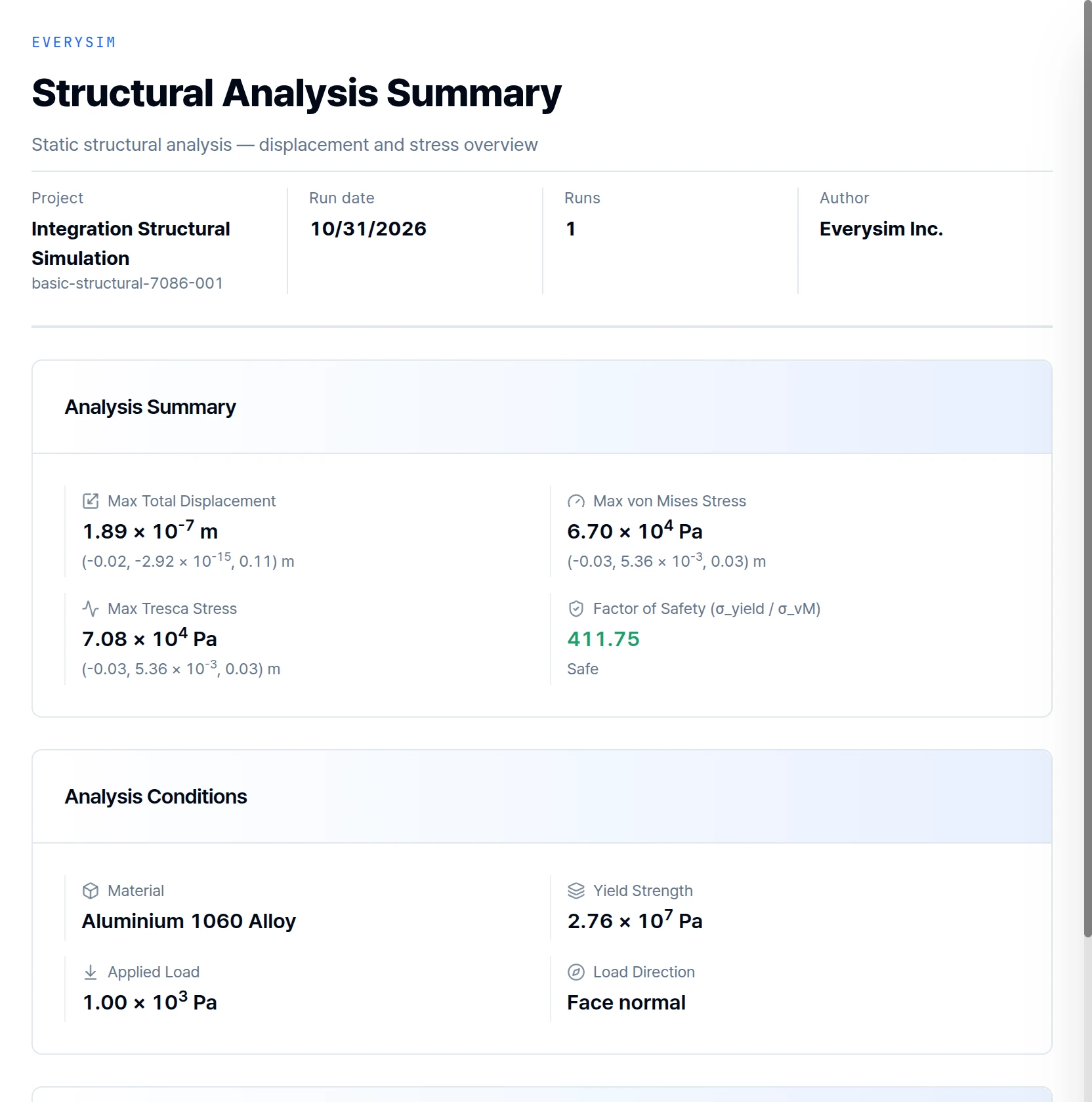
The report consolidates Max Total Displacement, Max von Mises Stress, Max Tresca Stress and Factor of Safety, with Analysis Conditions, Engineering Insights and Key Results. The critical-node charts provide a compact numerical review alongside the 3D result. A Factor of Safety below 1 means the peak von Mises stress exceeds the yield strength, and the report marks this as Yields.
Use these values only after confirming that the geometry, material assignment, contacts, constraints, loads and mesh accurately represent the case being studied.
Need Assistance or Have Questions?
Frequently Asked Questions: FAQ Link
Support Inquiries: support@everysim.io