4.9 Rapid Aerodynamics: Body-Only
A Body-Only project moves through Geom, Physics, Solve, Results and Report. There is no model or mesh step. The workbench header shows this workflow as Vortex > Vortex Lattice, and the auto-generated project title does not name the mode.
1. Geometry: Upload CAD
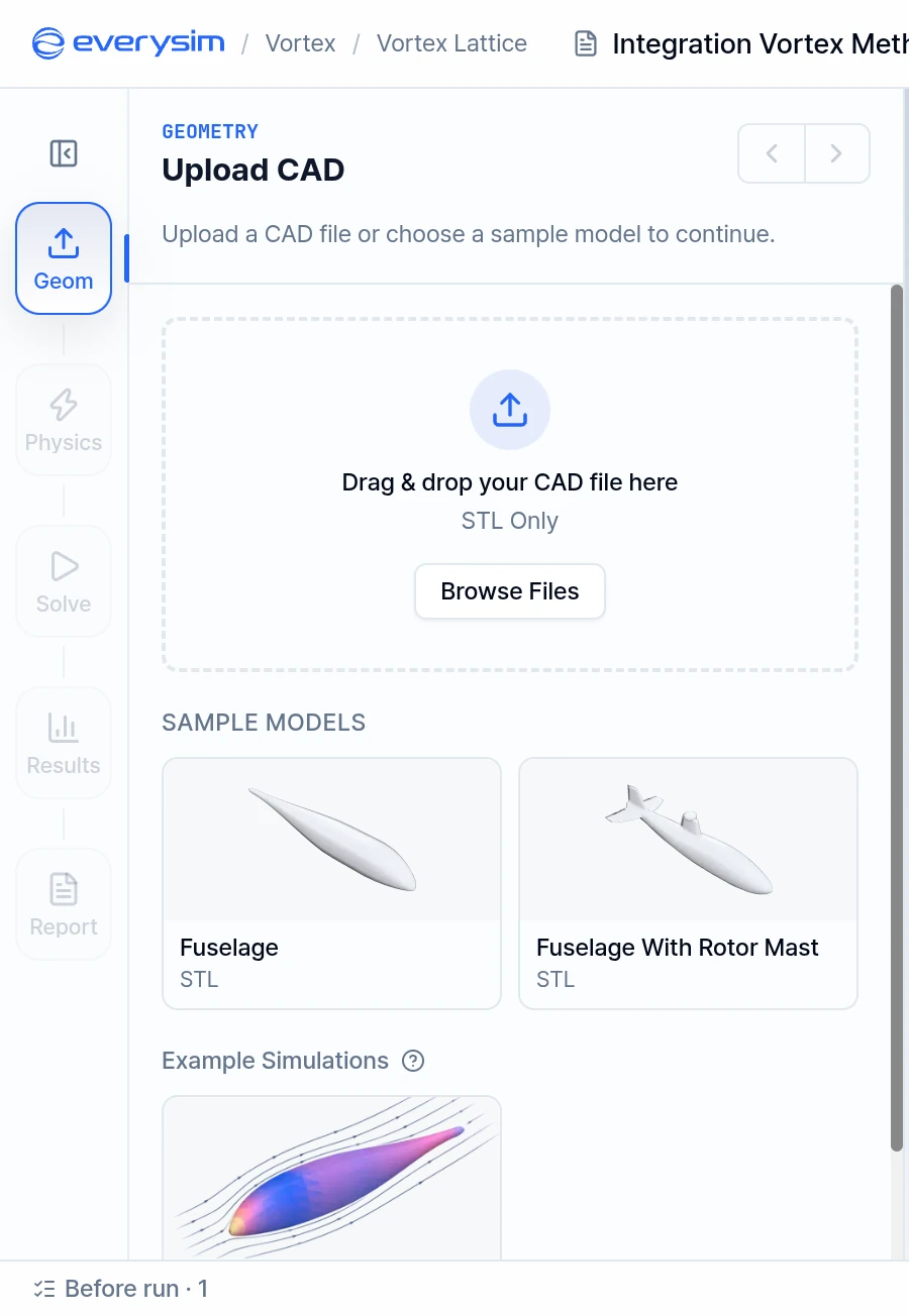
In the Upload CAD panel, you can import the body geometry used for Rapid Aerodynamics analysis. Drag and drop an STL file into the upload area, or click Browse Files to select the file from your computer. If you do not have a prepared file, choose Fuselage or Fuselage With Rotor Mast under Sample Models to continue the workflow with a sample body model. Choose the file's unit when asked; samples use their own unit.
The upload has these limits:
- Only STL files are accepted, with up to 4000 surface elements.
- The file must not contain duplicate, overlapping or degenerate triangles or non-manifold edges. Otherwise the upload stops with The STL geometry needs repair.
After the body is imported, the model is displayed in the 3D viewer. Use Moments About (Geometry Origin or Custom Point) to set the point that the report takes moments about, then continue to the next step.
2. Physics: Flow Settings
In the Physics / Model panel, Flow Settings defines the incoming flow direction and speed. Click Next: Solve when they are set.
- Direction: Selects the axis direction of the incoming airflow: X Axis (default), Y Axis, Z Axis or their negative directions.
- Wind Speed: Sets the flow speed used in the simulation, in the unit of the project's unit system. It must be at least 0.3 m/s and must not exceed Mach 0.7 (240.1 m/s). A new project starts at 0.3 m/s. To solve several speeds as one batch, use Batch on this field.
3. Solve: Run Simulation
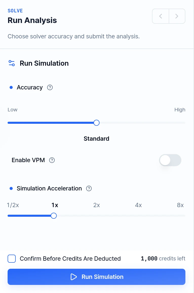
In the Run Analysis panel, you can set the solver options before running the analysis.
3.1. Accuracy
The Accuracy slider, from Low to High, controls the balance between speed and accuracy. Higher accuracy gives more precise results but takes longer and uses more credits.
- Fast: Runs the simulation quickly with lower computational cost.
- Standard (default): Provides a balanced setting for general aerodynamic review.
- Accurate: Uses a higher accuracy setting when more detailed results are needed.
Enable VPM turns on the Vortex Particle Method. It is off by default and available only at Standard or Accurate. Accumulating many particles can increase computation time and memory use.
3.2. Simulation Acceleration
The Simulation Acceleration slider (1/2x to 8x) sets the compute resources used. Higher acceleration uses more resources and consumes credits faster, while 1/2x uses fewer credits but can be much slower. The available stops depend on your plan's core limit.
After checking the imported body, direction, wind speed and accuracy, click Run Simulation to start the Rapid Aerodynamics analysis. Credits are deducted for the run. Select Confirm Before Credits Are Deducted to review the charge first.
4. Results
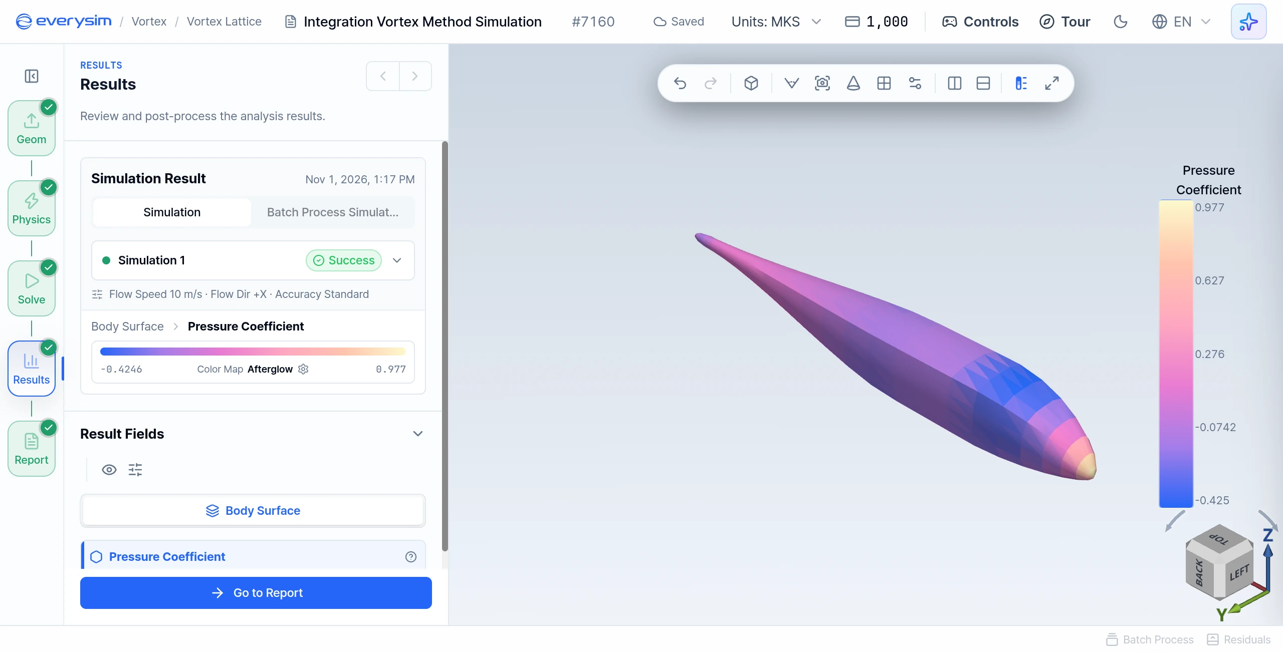
When the simulation is complete, the Results step shows Body Surface > Pressure Coefficient as a colored contour on the imported body. The contour shows how the pressure coefficient changes across the body surface.
Use the 3D viewer to rotate, zoom, and inspect the result from different angles. This allows you to check the overall aerodynamic trend around the body and identify regions where the computed values are relatively higher or lower.
5. Report
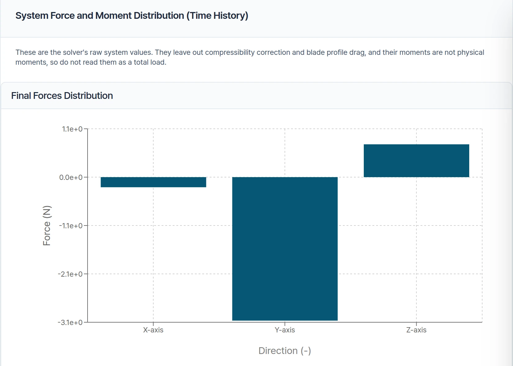
The report summarizes the final aerodynamic forces acting on the imported body. The card is titled System Force and Moment Distribution (Time History), but for Body-Only projects it draws only the Final Forces Distribution bar chart, without moments or a time history. The chart separates the integrated load into the X, Y, and Z directions so the dominant body force can be identified at a glance.
Keep two limits in mind when reading these values:
- Body loads are inviscid panel-method pressure loads and do not include skin friction.
- If the report marks the values as the solver's raw system values, do not read them as a total load.
Need Assistance or Have Questions?
Frequently Asked Questions: FAQ Link
Support Inquiries: support@everysim.io